Grove - I2C Color Sensor
Introduction
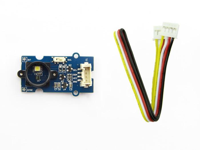
This module is based on the color sensor TCS3414CS with digital output I2C. Based on the 8*2 array of filtered photodiodes and 16-bit analog-to-digital converters, you can measure the color chromaticity of ambient light or the color of objects. Of the 16 photodiodes, 4 have red filters, 4 have green filters, 4 have blue filters and 4 have no filter(clear). With the synchronization input pin, an external pulsed light source can provide precise synchronous conversion control.
Note
Please note that the latest version V2.0 has replaced the IC with TCS3472 and the old library has also been updated, If you are using the V2.0 version, please use the new library.
Version
| Revision | Descriptions | Release | How to buy |
|---|---|---|---|
| v1.2 | Initial public release (beta) | Jan 17, 2013 |  |
| v2.0 | Replace TCS3472(EOL) with TCS34725FN and optimize PCB Layout | Apr 27,2017 | |
Features
- Grove compatible interface
- 16-Bit digital output with I2C
- SYNC Input Synchronizes Integration Cycle to Modulated Light Sources
- Operating temperature range -40°C to 85°C
- Programmable interrupt function with User-Defined Upper and lower threshold settings
- RoHS Compliant
Tip
More details about Grove modules please refer to Grove System
Specifications
| Parameter | Value/Range |
|---|---|
| PCB Size | 2.0 cm * 4.0 cm |
| Interface | 2.0mm pitch pin header |
| VCC | 3.3 - 6.0 V |
| I2C Speed | 400 kHz |
Platforms Supported
Getting Started
Following documents help in getting the user started with Grove.
Hardware Connections
Grove products have an eco system and all have the same connector which can plug onto the Grove Base Shield. Connect this module to the I2C port of Base Shield. However, you can also connect Grove - I2C Color Sensor to Arduino without Base Shield by jumper wires.
| Arduino UNO | Grove - I2C Color Sensor |
|---|---|
| 5V | VCC |
| GND | GND |
| SDA | SDA |
| SCL | SCL |
Software Installation
Download Arduino and install Arduino driver
Getting Started with Seeeduino/Arduino
Demos
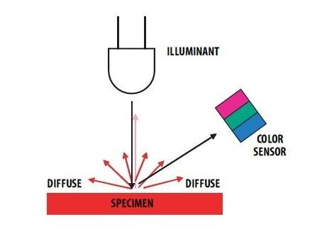
This module can be used to detect the color of light source or the color of objects. When used to detect the color of the light source, the led switch should be turned off, and the light source should shine the sensor directly. When used to detect the color of things, the led should be on and you should put the object on the top of the enclosure closely. The theory of sensing the color of objects is Reflective Sensing Theory. Like the picture below.
Color Sensor Library
We have created a library to help you start playing quickly with the Seeeduino/Arduino, in this section we’ll show you how to set up the library.
Setup
- Download the library code as a zip file from the Grove_I2C_Color_Sensor github page. If you are using the latest version V2.0(IC is TCS3472 ), please use this new library
- Unzip the downloaded file into your …/arduino/libraries.
- Rename the unzipped folder “Color_Sensor”
- Start the Arduino IDE (or restart if it is open).
Description of function
This is the most important/useful function in the library, we invite you to look at the .h and .cpp files yourself to see all the functions available.
Read RGB data through the library function
readRGB(int *red, int *green, int *blue)
- red: The variable address to save R.
- green: The variable address to save G.
- blue: The variable address to save B.
void loop()
{
    int red, green, blue;
    GroveColorSensor colorSensor;
    colorSensor.ledStatus = 1;            // When turn on the color sensor LED, ledStatus = 1; When turn off the color sensor LED, ledStatus = 0.
    while(1)
    {
        colorSensor.readRGB(&red, &green, &blue);    //Read RGB values to variables.
        delay(300);
        Serial.print("The RGB value are: RGB( ");
        Serial.print(red,DEC);
        Serial.print(", ");
        Serial.print(green,DEC);
        Serial.print(", ");
        Serial.print(blue,DEC);
        Serial.println(" )");
        colorSensor.clearInterrupt();
    }
}
Color Sensor Examples/Applications
This example shows how to use features of Grove - I2C Color Sensor and display the detected color with a Chainable RGB LED Grove.
Note
If you haven't downloaded Grove-Chainable RGB LED library to your Arduino IDE before, please download and set up the library first.- Open File->Examples->Color_Sensor->example->ColorSensorWithRGB-LED sketch for a complete example, or copy and paste code below to a new Arduino sketch.
Description: This example can measure the color chromaticity of ambient light or the color of objects, and via Chainable RGB LED Grove, display the detected color.
You also can use other display modules to display the detected color by Grove - I2C Color Sensor.
#include <Wire.h>
#include <GroveColorSensor.h>
#include <ChainableLED.h>

#define CLK_PIN   7
#define DATA_PIN  8
#define NUM_LEDS  1            //The number of Chainable RGB LED

ChainableLED leds(CLK_PIN, DATA_PIN, NUM_LEDS);

void setup()
{
    Serial.begin(9600);
    Wire.begin();
}

void loop()
{
    int red, green, blue;
    GroveColorSensor colorSensor;
    colorSensor.ledStatus = 1;            // When turn on the color sensor LED, ledStatus = 1; When turn off the color sensor LED, ledStatus = 0.
    while(1)
    {
        colorSensor.readRGB(&red, &green, &blue);    //Read RGB values to variables.
        delay(300);
        Serial.print("The RGB value are: RGB( ");
        Serial.print(red,DEC);
        Serial.print(", ");
        Serial.print(green,DEC);
        Serial.print(", ");
        Serial.print(blue,DEC);
        Serial.println(" )");
        colorSensor.clearInterrupt();
        for(int i = 0; i<NUM_LEDS; i++)
        {
            leds.setColorRGB(i, red, green, blue);
        }
    }
}
- Upload the code to the development board.
- Then Grove_-_Chainable_RGB_LED would display the color which is detected.
Other Reference
This module is based on the color sensor TCS3414CS. The TCS3414CS digital color sensor returns data from four channels: red(R), green(G), blue(B) and clear(C)(non-filtered). The response from the red, green and blue channels (RGB) can be used to determine a particular source’s chromaticity coordinates (x, y). These standards are set by the Commission Internationale de l’Eclairage (CIE). The CIE is the main international organization concerned with color and color measurement.In order to acquire the color of a given object using TCS3414CS, we must first map the sensor response (RGB) to the CIE tristimulus values (XYZ). It is then necessary to calculate the chromaticity coordinates (x, y).
![]()
Chromaticity Calculation Process Overview
The equations to do the transformation:
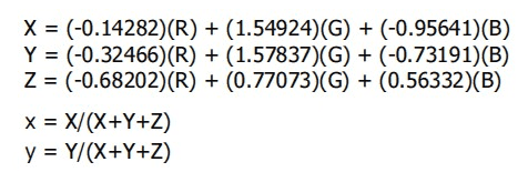
Transformation Equations
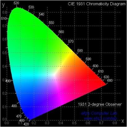
- When we get coordinates (x, y), please reference the below figure so as to get the recommended color.
Resources
- [Library]Library for Grove - I2C Color Sensor V1.2
- [Library]Library for Grove - I2C Color Sensor V2.0
- [Eagle]Grove-I2C Color Sensor Eagle File V1.2
- [Eagle]Grove-I2C Color Sensor Eagle File V2.0
- [PDF]Grove-I2C Color Sensor SCH File V1.2
- [PDF]Grove-I2C Color Sensor SCH File V2.0
- [PDF]Grove-I2C Color Sensor PCB File V1.2
- [PDF]Grove-I2C Color Sensor PCB File V2.0
- [Datasheet]TCS3414-A Datasheet
- [Datasheet]TCS3472 Datasheet
| Arduino | Wio | BeagleBone | Raspberry Pi | LinkIt ONE |
|---|---|---|---|---|
Caution
The platforms mentioned above as supported is/are an indication of the module's hardware or theoritical compatibility. We only provide software library or code examples for Arduino platform in most cases. It is not possible to provide software library / demo code for all possible MCU platforms. Hence, users have to write their own software library.
Help us make it better
Welcome to the new documentation system of Seeed Studio. We have made a lot of progress comparing to the old wiki system and will continue to improve it to make it more user friendly and helpful. The improvement can't be done without your kindly feedback. If you have any suggestions or findings, you are most welcome to submit the amended version as our contributor via Github or give us suggestions in the survey below, it would be more appreciated if you could leave your email so that we can reply to you. Happy Hacking!