Base Shield V2
Introduction

Arduino Uno is the most popular Arduino board so far, however it is sometimes frustrating when your project requires a lot of sensors or Leds and your jumper wires are in a mess. The purpose of creating the Base Shield is to help you get rid of bread board and jumper wires. With the rich grove connectors on the base board, you can add all the grove modules to the Arduino Uno conveniently! The pinout of Base Shield V2 is the same as Arduino Uno R3, however Arduino Uno is not the board one that the Base Shield V2 is compatible with plenty of boards.

Version
| Product Version | Changes | Released Date |
|---|---|---|
| Base Shield V1.2 | Initial | Oct 2011 |
| Base Shield V1.3 | Change the Grove connector layout and quantity | Aug 2012 |
| Base Shield V2.0 | Change the Grove connector layout and quantity, as well as a power switch to enable both 3.3V and 5V. | Mar 2014 |
Compatible Boards
The Base Shield is tested and fully compatible with following boards:
- Arduino Uno(all revisions)/Seeeduino(V4&V4.2)
- Arduino Mega/Seeeduino Mega
- Arduino Zero(M0)/Seeeduino Lorawan
- Arduino Leonardo/Seeeduino Lite
- Arduino 101
- Arduino Due 3.3V
- Intel Edison 5V
- Linkit One
Note
The boards are not listed above mean that it might have chance to work with the platform board however requires extra work such as jump wires or rewriting the code. If you are interested in digging more, welcome to contact techsupport@seeed.cc.
Hardware Overview

- 1-Analog Ports: include 4 anlog ports, A0, A1, A2 and A3.
- 2-Digital Ports: include 7 digital ports, D2, D3, D4, D5, D6, D7 and D8.
- 3-UART Port: 1 UART port.
- 4-I2C Ports: 4 I2C ports.
- 5-Power Switch: when using Arduino UNO with Base Shield v2, please turn the switch to 5v position; While using Seeeduino Arch with Base Shield v2, please turn the switch to 3.3v.
- 6-Reset Buton: reset the arduino board.
- 7-PWR LED:The Green LED turns on when power on.
- 8-P1, P2:please solder the pads P1 and P2, if use Base Shield v2 with Seeeduino V3.
- Dimension: 2.1 * 2.7 inch
Getting Started
Hardware
- Step 1. Prepare the below stuffs:
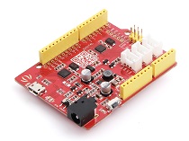
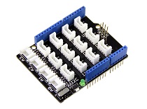
| Seeeduino V4.2 | Base Shield | Grove - Buzzer | Grove - Button |
|---|---|---|---|
 |
 |
 |
 |
| Get ONE Now | Get ONE Now | Get ONE Now | Get ONE Now |
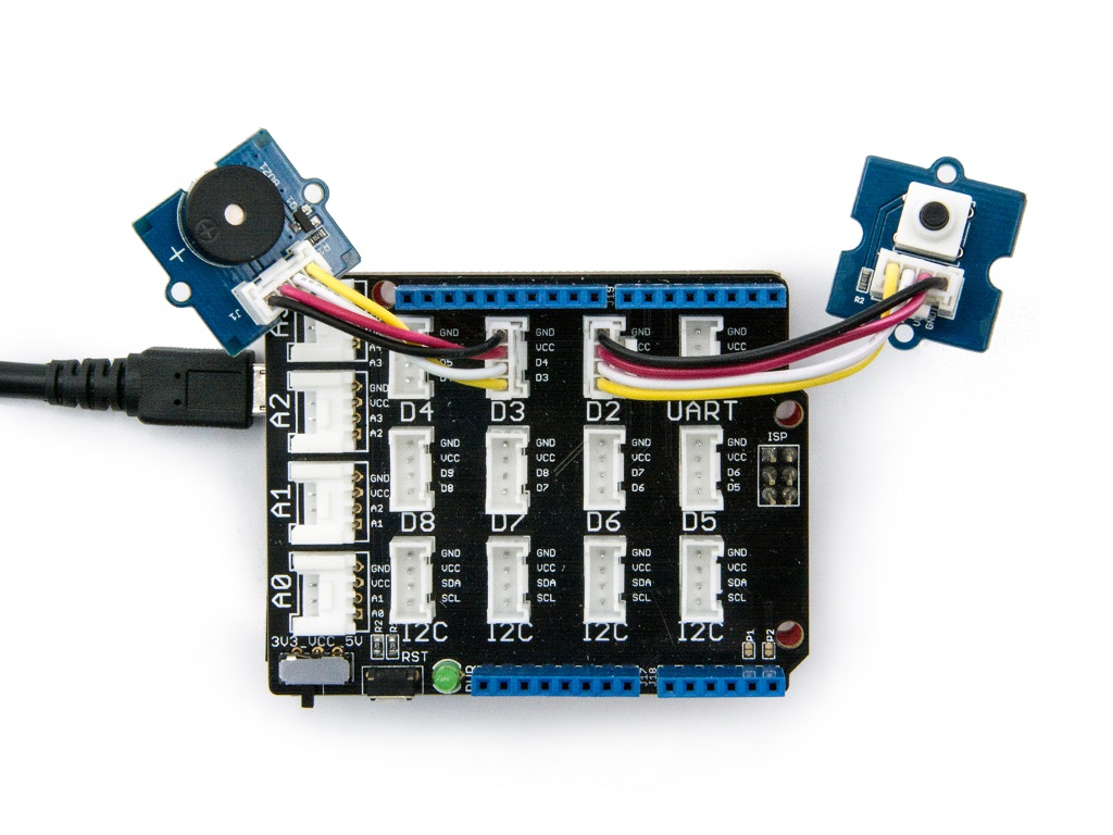
- Step 2. Connect Grove - Buzzer to port D3 of Base Shield.
- Step 3. Connect Grove - Button to port D2 of Base Shield.
- Step 4. Plug Base Shield into Seeeduino.
- Step 5. Connect Seeeduino to PC through a USB cable.
Software
- Step 1. Copy below code to Arduino IDE and upload to Seeeduino.
const int button = 2;       // connect a button
const int buzzer = 3;       // connect a buzzer
void setup()
{
    pinMode(button, INPUT); //set button as an INPUT device
    pinMode(buzzer, OUTPUT);   //set LED as an OUTPUT device
}
void loop()
{
    int btn = digitalRead(button); //read the status of the button
    digitalWrite(buzzer, btn);
    delay(10);
}
- Step 2. Press the button and we will hear the buzzer.
FAQ
Please click here to see all Base Shield V2 FAQs.
Tech Support
Please do not hesitate to contact techsupport@seeed.cc if you require further information.
Resources
- [PDF] Download Wiki PDF
- [Eagle] Base Shiled V2 SCH
- [Eagle] Base Shiled V2 PCB
- [PDF] Base Shiled V2 SCH
- [PDF] Base Shiled V2 PCB
Help us make it better
Welcome to the new documentation system of Seeed Studio. We have made a lot of progress comparing to the old wiki system and will continue to improve it to make it more user friendly and helpful. The improvement can't be done without your kindly feedback. If you have any suggestions or findings, you are most welcome to submit the amended version as our contributor via Github or give us suggestions in the survey below, it would be more appreciated if you could leave your email so that we can reply to you. Happy Hacking!