Grove - 2-Coil Latching Relay
Introduction
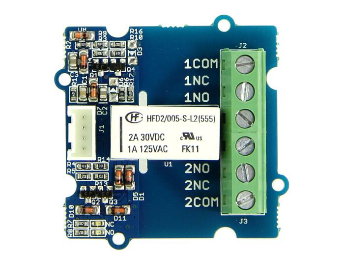
This module is based on 2-Coil Latching Relay. Contrast to the ordinary relay, this latching relay does not need continuous power to keep the state, only a rising/falling pulse is needed to change the work state. Even the power can be removed when the work state do not need to change, making this module especially suitable for low-power projects.

Features
- Grove Connector
- Low power consumption
- Dual Switch
Tip
More details about Grove modules please refer to Grove System
Specifications
| Item | Min | Typical | Max | Unit |
|---|---|---|---|---|
| Working Voltage | 4.7 | 5.0 | 5.3 | VDC |
| Set/Reset Voltage(Max) | 4.0 | VDC | ||
| Coil Resistance | 151 | 167 | 183 | Ω |
| Switching Voltage(Max) | 35VAC/35VDC | / | ||
| Switching Current(Max) | 3 | A | ||
| Set Time(Latching) | 4.5(max) | ms | ||
| Reset Time(Latching) | 3.5(max) | ms | ||
Platforms Supported
Before usage
Related Reading
We suggest you to read those knowledge before using the Gas sensor, it’ll help you to learn more about Arduino and our products, and also it’ll let you to use open souse hardware more easier.
After reading that you will know how to use Base shield with Grove products to work well with Arduino. Let’s start it !
To be prepared
This tutorial will include some necessary products:
- Arduino UNO R3 or Seeeduino v4
- Base Shield
- Grove - 2-Coil Latching Relay
Getting Started
With Arduino
The latching relay only draws power during the changing of state. A rising/falling voltage pulse on the signal pin changes it’s working state. This is very useful in situations where energy efficiency is important, and also in situations where you need the relay to remember its state.
Let’s begin to use it.
- Connect the module to D3 port of Grove - Base Shield.
- The relay hold in “set” status(Comm and NO connected) in default, when there is a rising edge on the SIG pin. It turns the “reset” state(Comm and NC connected). The reference code is shown below:
#define LatchingRelay 3
void setup()
{
    pinMode(LatchingRelay,OUTPUT);

    digitalWrite(LatchingRelay,LOW);
    delay(1000);
    digitalWrite(LatchingRelay,HIGH);
    delay(1000);
}
void loop()
{

}
- The relay hold in “reset” status(Comm and NC Connected), when there is a falling edge on the SIG pin. It turns the “set” state(Comm and NO connected). The reference code is shown below:
#define LatchingRelay 3
void setup()
{
    pinMode(LatchingRelay,OUTPUT);

    digitalWrite(3,HIGH);
    delay(1000);
    digitalWrite(3,LOW);
    delay(1000);
}
void loop()
{

}
- This module consumes little power when working state doesn’t change. After setting the relay state, you do not need to supply power for the Latching Relay any more, which makes it especially low power consumption.
Note
Relay is on the "reset" status when being released from stock.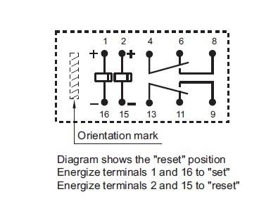
Notes
1. The two-way relays are controlled at the same time.
2. The NO(NC) indicator will flash once when switch to "set"("reset") status.
With Raspberry Pi
1.You should have got a raspberry pi and a grovepi or grovepi+.
2.You should have completed configuring the development enviroment, otherwise follow here.
3.Connection
- Plug the sensor to grovepi socket D4 by using a grove cable.
4.Navigate to the demos’ directory:
cd yourpath/GrovePi/Software/Python/
- To see the code
nano grove_2_coil_latching_relay.py # "Ctrl+x" to exit #
import time
import grovepi

# Connect the Grove 2-Coil Latching Relay to digital port D4
# SIG,NC,VCC,GND
relay = 4

grovepi.pinMode(relay,"OUTPUT")

while True:
    try:
        # switch on for 5 seconds
        grovepi.digitalWrite(relay,1)
        print "on"
        time.sleep(5)

        # switch off for 5 seconds
        grovepi.digitalWrite(relay,0)
        print "off"
        time.sleep(5)

    except KeyboardInterrupt:
        grovepi.digitalWrite(relay,0)
        break
    except IOError:
        print "Error"
5.Run the demo.
sudo python grove_2_coil_latching_relay.py
Resources
| Arduino | Wio | BeagleBone | Raspberry Pi | LinkIt ONE |
|---|---|---|---|---|
Caution
The platforms mentioned above as supported is/are an indication of the module's hardware or theoritical compatibility. We only provide software library or code examples for Arduino platform in most cases. It is not possible to provide software library / demo code for all possible MCU platforms. Hence, users have to write their own software library.
Help us make it better
Welcome to the new documentation system of Seeed Studio. We have made a lot of progress comparing to the old wiki system and will continue to improve it to make it more user friendly and helpful. The improvement can't be done without your kindly feedback. If you have any suggestions or findings, you are most welcome to submit the amended version as our contributor via Github or give us suggestions in the survey below, it would be more appreciated if you could leave your email so that we can reply to you. Happy Hacking!