Grove System
Introduction
What is the Grove System?
Grove is a modular, standardized connector prototyping system. Grove takes a building block approach to assembling electronics. Compared to the jumper or solder based system, it is easier to connect, experiment and build and simplifies the learning system, but not to the point where it becomes dumbed down. Some of the other prototype systems out there takes the level down to building blocks. Good stuff to be learned that way, but the Grove system allows you to build real systems. It requires some learning and expertise to hook things up.
The Grove system consists of a base unit (stem) and various modules (twigs) with standardized connectors. The people originating the Grove system (Seeedstudio) have tried to use “stems”and “twigs” as part of the Grove lexicon. After a short period of consideration, we are dropping those names. They just aren’t needed and just confuse the issue.
The Base unit, generally a microprocessor, allows for easy connection of any input or output from the Grove modules. And every Grove module typically addresses a single function, such as a simple button or a more complex heart rate sensor.
You don’t need a Base unit to connect up to Grove modules. You can use a cable (Grove to Pin Header Converter) to run from the pins on the Raspberry Pi or Arduino to the Grove connectors.
Grove Projects
Here are some project made with Grove for your reference, more projects please refer to Recipe or Instructables.
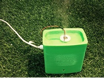
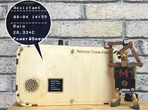
| DIY a Humidifier | Personal Voice Assistant | Acrylic Monitor Stand |
|---|---|---|
 |
 |
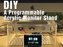 |
| MAKE IT NOW! | MAKE IT NOW! | MAKE IT NOW! |
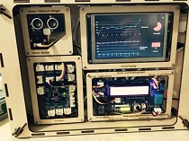
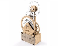
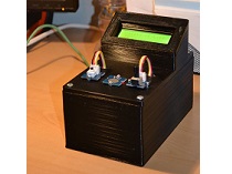
| Sensor hub & Win10 IoT | Steam-punk Style Award | Plant Watering Device |
|---|---|---|
 |
 |
 |
| MAKE IT NOW! | MAKE IT NOW! | MAKE IT NOW! |
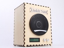
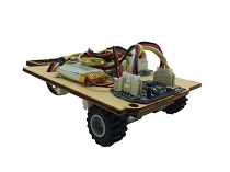
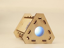
| Wi-Fi Speaker | DIY a toy car | Retro Wooden Lamp |
|---|---|---|
 |
 |
 |
| MAKE IT NOW! | MAKE IT NOW! | MAKE IT NOW! |
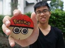
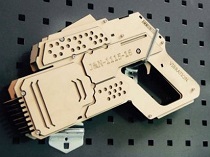
| Pokemon Go SAFETY BADGE | Make a Wooden Gun | Quality of Life Meter |
|---|---|---|
 |
 |
 |
| MAKE IT NOW! | MAKE IT NOW! | MAKE IT NOW! |
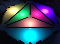
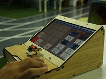
| Hackable RGB ornament | The Internet Of Led Wall | PI Game Box |
|---|---|---|
 |
 |
 |
| MAKE IT NOW! | MAKE IT NOW! | MAKE IT NOW! |
Size of Grove
There’re 5 size of Grove.
| 1X1 | 1X2 | 1X3 | 2X2 | 2X3 |
|---|---|---|---|---|
| 20x20mm | 20x40mm | 20x60mm | 40x40mm | 40x60mm |
 |
 |
 |
 |
 |
How to connect Grove to your board
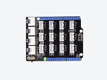
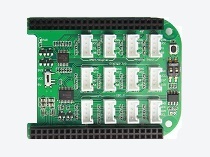
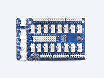
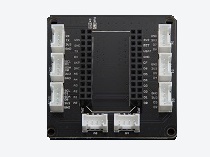
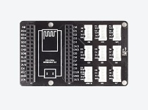
If there’s no Grove connector on your board, you need a Grove Expansion Board which to attach the Grove modules. The Grove Expansion Board provides the processing power, and the modules offer the input sensors and output actuators of your system. There are many Grove Expansion Board for different platform already, they include Arduino UNO, Particle Phone, BeagleBone board etc.
| Arduino Base Shield | BeagleBone board | Arduino Mega |
|---|---|---|
 |
 |
 |
| BUY ONE NOW! | BUY ONE NOW! | BUY ONE NOW! |
| IOIO-OTG | Particle Photon | NodeMCU |
|---|---|---|
 |
 |
 |
| BUY ONE NOW! | BUY ONE NOW! | BUY ONE NOW! |
Note
Arduino Base Shield works for:
- Arduino UNO/Leonardo
- Seeeduino V3/4/4.1/Lite/Clio/Lotus/Stalker
- LinkIt ONE
Interface of Grove modules
You may notice that there’re 4 color of the Grove cable.
- pin 1 - Yellow (for example, SCL on I2C Grove Connectors)
- pin 2 - White (for example, SDA on I2C Grove Connectors)
- pin 3 - Red - VCC on all Grove Connectors
- pin 4 - Black - GND on all Grove Connectors
There’re mainly 4 type of Interface of Grove modules.
Digital
A digital Grove connector consists of the standard four lines coming into the Grove plug. The two signal lines are generically called D0 and D1. Most modules only use D0, but some do (like the LED Bar Grove display) use both. Often base units will have the first connector called D0 and the second called D1 and they will be wired D0/D1 and then D1/D2, etc.
Examples of Grove Digital modules are: Switch Modules, the Fan Module, and the LED Module. In Figure 8, you can see what the Grove connector looks like on the schematic for the LED Grove module. They range from the simple to the very complex.
| pin | Function | Note |
|---|---|---|
| pin1 | Dn | Primary Digital Input/Output |
| pin2 | Dn+1 | Secondary Digital Input/Output |
| pin3 | VCC | Power for Grove Module, 5V/3.3V |
| pin4 | GND | Ground |
Grove Analog
An Grove Analog connector consists of the standard four lines coming into the Grove plug. The two signal lines are generically called A0 and A1. Most modules only use A0. Often base units will have the first connector called A0 and the second called A1 and they will be wired A0/A1 and then A1/A2, etc.
| pin | Function | Note |
|---|---|---|
| pin1 | An | Primary Analog Input |
| pin2 | An+1 | Secondary Analog Input |
| pin3 | VCC | Power for Grove Module, 5V/3.3V |
| pin4 | GND | Ground |
Grove UART
The Grove UART module is a specialized version of a Grove Digital Module. It uses both Pin 1 and Pin 2 for the serial input and transmit. The Grove UART plug is labeled from the base unit point of view. In other words, Pin 1 is the RX line (which the base unit uses to receive data, so it is an input) where Pin 2 is the TX line (which the base unit uses to transmit data to the Grove module).
| pin | Function | Note |
|---|---|---|
| pin1 | RX | Serial Receive |
| pin2 | TX | Serial Transmit |
| pin3 | VCC | Power for Grove Module, 5V/3.3V |
| pin4 | GND | Ground |
Grove I2C
Those long term readers of this blog know that our favourite devices are I2C sensors. There are many types of I2C Grove sensors available. Most are 5V/3.3V devices, but there are a few that are only 3.3V or 5.0V. You need to check the specifications.
The Grove I2C connector has the standard layout. Pin 1 is the SCL signal and Pin 2 is the SDA signal. Power and Ground are the same as the other connectors. This is another special version of the Grove Digital Connector. In fact, often the I2C bus on a controller (like the ESP8266, Raspberry Pi and the Arduino) just uses Digital I/O pins to implement the I2C bus. The pins on the Raspberry Pi and Arduino are special with hardware support for the I2C bus.
| pin | Function | Note |
|---|---|---|
| pin1 | SCL | I2C Clock |
| pin2 | SDA | I2C Data |
| pin3 | VCC | Power for Grove Module, 5V/3.3V |
| pin4 | GND | Ground |
Grove Cables
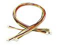
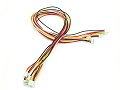
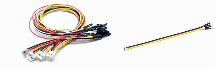
Normal Grove Cable
There’re 4 size of Grove cables for your projects, the length is consist of 5cm, 20cm, 30cm, 40cm as well as 50 cm. As shown below.
| 5cm | 20 cm | 30 cm | 40 cm | 50 cm |
|---|---|---|---|---|
 |
 |
 |
 |
 |
| BUY ONE NOW! | BUY ONE NOW! | BUY ONE NOW! | BUY ONE NOW! | BUY ONE NOW! |
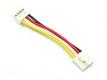
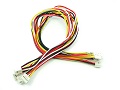
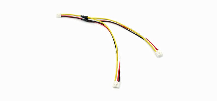
Grove - Branch Cable
Grove Branch Cable is a cable used in the Grove system. It consists of three male-type latching connectors and four color-coded wires. Grove Branch Cables can be used to support daisy-chaining multiple Grove devices to a Grove shield. Typically, one end is connected to a Grove shield, and the second and third connectors are attached to two Grove devices.
As with other members of the Grove cable family, the male connectors are keyed. This means that they are shaped uniquely and will fit one and only one way into their matching connectors on shields and devices. Also, when attaching the connectors to shields or devices, be sure to press firmly to mate the male connectors on the Grove Branch Cable with the female receptacles on the Grove shield or Grove devices. Since Grove Branch Cables have latches (sometimes referred to as “buckles” or “buckled cables”), when the latch closes, you will hear a small sound and should see the latch close over its corresponding part. These latches (or buckles) improve connections, and are especially handy in high-vibration or production environments, since some force must be used when disconnecting the cable. When moving your Grove device, or changing it, you must also apply a small bit of pressure to release the latch on the Grove Branch Cable connector, and then pull to remove the it from the receptacle or socket.
Use extra care if connecting multiple devices using the Grove Branch Cable. Be aware that the analog or digital pin on the Grove Shield will be shared by both Grove devices. Such configurations may be inappropriate for two analog devices. Using a Grove Branch Cable to connect an analog and a digital Grove device may not work at all.
Sample applications include:
- Connecting or daisy chaining two or more I2C devices. Multiple branch cables can be used to extend I2C busses.
- Connecting two devices that need to work at the same time. For example, a LED and a Relay could be connected to a Grove Shield using a single Grove Branch Cable. It would then be possible to turn both the LED and the Relay off or on simultaneously since the two devices would be controlled by a single digital pin.
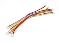
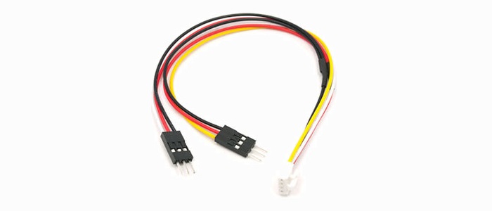
Grove - Branch Cable for Servo
Grove Branch Cable for Servos are another type of Grove Cable, and are primarily used to connect one or two servos to your project. They consist of three connectors: one keyed four pin male connector suitable for connecting to a Grove Shield, and two three pin male post-type connectors. In this configuration, power and ground (pins 3 and 4 from the four pin male) are carried to both three pin male connectors. Pin 1 (yellow)of the four pin connector is connected to one of the pins of the Arduino capable of PWM, and is carried out to one of the three pin male post connectors. Pin 2 (white wire) of the four pin connector is also connected to a second PWM-capable pin of the Arduino, and is carried out to the second three pin male post connector.
The four pin keyed connector of the Grove Branch Cable for Servos will usually be connected to a Grove Shield digital socket such as D2-D9. When connecting servos, make a note of the wire color of the digital PWM cable (yellow or white) to know which digital pin corresponds to the servo input.
Grove to 4pin Female/Male Jumper
You can use it for:
- Connect Grove device to the other MCUs, such as you want to connect Grove - Light Sensor to Raspberry Pi.
- Use Base Shield to control some non-grove device
Link to buy a cable
| Cable | Link |
|---|---|
| Branch Cable | BUY ONE NOW! |
| Branch Cable for Servo | BUY ONE NOW! |
| Grove to 4Pin Female | BUY ONE NOW! |
| Grove to 4Pin Male | BUY ONE NOW! |
Grove Starter Kit
We designed many kits for the beginner. Normally, a Grove starter kit include a Grove Extension Board, many Grove modules and a user manual, which include many lessons for the beginners. If you want to start a platform or just learn about electronic, Grove Starter kit is your best choice.
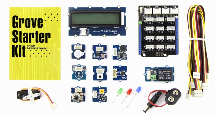
There are many kits for different platform.
| Kit Name | Link |
|---|---|
| Grove - Starter Kit for Arduino | BUY ONE NOW! |
| Grove Starter Kit for mbed | BUY ONE NOW! |
| Grove Starter Kit for LinkIt ONE | BUY ONE NOW! |
| Grove Starter Kit for LaunchPad | BUY ONE NOW! |
| Grove Starter Kit for Photon | BUY ONE NOW! |
| Grove Starter Kit for BeagleBone Green | BUY ONE NOW! |
| Grove Starter Kit for LinkIt 7688 Duo | BUY ONE NOW! |
| Grove Starter Kit for 96Boards | BUY ONE NOW! |
| Grove Starter kit for Arduino&Genuino 101 | BUY ONE NOW! |
| GrovePi+ Starter Kit for Raspberry Pi | BUY ONE NOW! |
Choose your Grove
Want some Grove modules for your project? Here are some recommend.
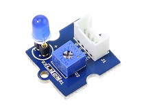
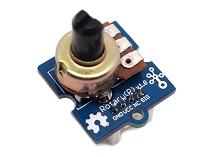
Grove Basic Input and Output
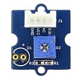
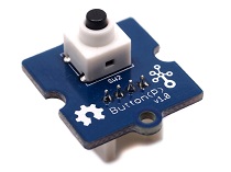
| Grove - LED | Grove - Rotary Angle Sensor | Grove - Button |
|---|---|---|
 |
 |
 |
| More Details | More Details | More Details |
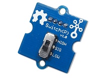
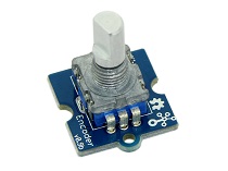
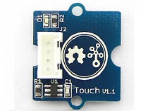
| Grove - Switch | Grove - Encoder | Grove - Touch Sensor |
|---|---|---|
 |
 |
 |
| More Details | More Details | More Details |
Grove for Display
| I2C_LCD | Grove - OLED Display 0.96” | Grove - OLED Display 1.12” |
|---|---|---|
 |
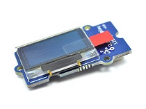 |
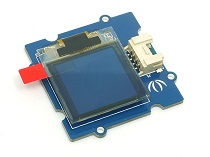 |
| More Details | More Details | More Details |
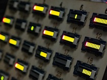
| Grove - LCD RGB Backlight | Grove - 4-Digit Display | Grove LED Bar v2.0 |
|---|---|---|
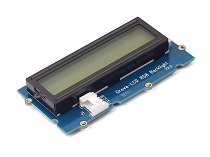 |
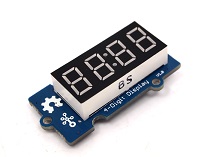 |
 |
| More Details | More Details | More Details |
Grove for Motion Detect
| Grove - IMU 10DOF v2.0 | Digital Accelerometer(±400g) | 3-Axis Digital Gyro |
|---|---|---|
 |
 |
 |
| More Details | More Details | More Details |
| 3-Axis Digital Compass | 3-Axis Digital Accelerometer(±1.5g) | 3-Axis Analog Accelerometer |
|---|---|---|
 |
 |
 |
| More Details | More Details | More Details |
| 3-Axis Digital Acc(±16g) | 6-Axis Acc&Compass v2.0 | 6-Axis Acc&Gyroscope |
|---|---|---|
 |
 |
 |
| More Details | More Details | More Details |
Grove for Communication
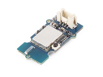
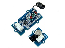
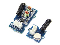
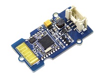
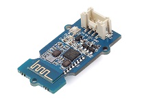
| Grove – Uart Wifi | 433MHz Simple RF link kit | 315MHz Simple RF Link Kit |
|---|---|---|
 |
 |
 |
| More Details | More Details | More Details |
| Grove - Serial RF Pro | 125KHz RFID Reader | Grove - BLE |
|---|---|---|
 |
 |
 |
| More Details | More Details | More Details |
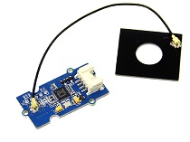
| Grove - BLE (dual model) | Grove - NFC | Grove - NFC Tag |
|---|---|---|
 |
 |
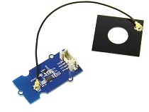 |
| More Details | More Details | More Details |
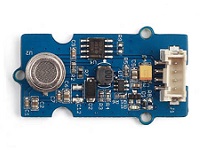
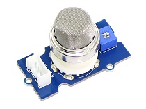
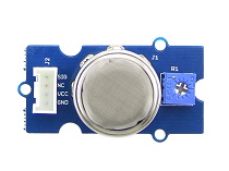
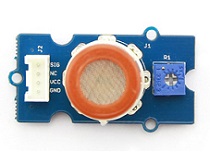
Grove for Environment
| Air quality sensor | Gas Sensor(MQ2) | Gas Sensor(MQ5) |
|---|---|---|
 |
 |
 |
| More Details | More Details | More Details |
| Gas Sensor(MQ3) | Gas Sensor(MQ9) | Gas Sensor(O2) |
|---|---|---|
 |
 |
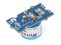 |
| More Details | More Details | More Details |
| Dust Sensor | Moisture Sensor | Temperature&Humidity Sensor |
|---|---|---|
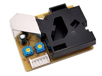 |
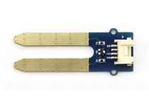 |
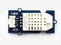 |
| More Details | More Details | More Details |
Grove for Robot
| I2C Mini Motor Driver | I2C Motor Driver | Grove - Servo |
|---|---|---|
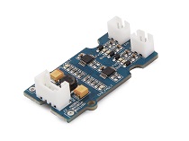 |
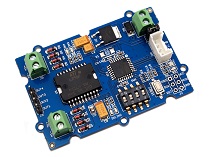 |
 |
| More Details | More Details | More Details |
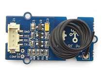
| Line Finder | Ultrasonic Ranger | 80cm Infrared Proximity Sensor |
|---|---|---|
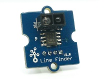 |
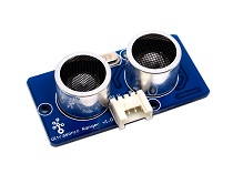 |
 |
| More Details | More Details | More Details |
Help us make it better
Welcome to the new documentation system of Seeed Studio. We have made a lot of progress comparing to the old wiki system and will continue to improve it to make it more user friendly and helpful. The improvement can't be done without your kindly feedback. If you have any suggestions or findings, you are most welcome to submit the amended version as our contributor via Github or give us suggestions in the survey below, it would be more appreciated if you could leave your email so that we can reply to you. Happy Hacking!