Grove - Variable Color LED
Introduction
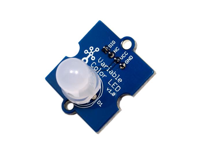
This Grove consists of one 8mm RGB LED. It operates at 5V DC. When SIG pin is logic HIGH, the RGB LED will light up. Perfect for use on Seeeduino digital outputs, or also can be controlled by pulse-width modulation. And it uses three adjustable resistor to change the color of the RGB LED.

Features
- Grove compatible
- Color adjustable
Tip
More details about Grove modules please refer to Grove System
Application Ideas
- Toys
- Decoration
Caution
Be gentle while adjusting the R, G and B adjustable resistances in case of over-turning.Specifications
| Item | Typical | Unit |
|---|---|---|
| Operate Voltage | 5.0 | VDC |
| Working Current | 20 | mA |
| Variable Resistor | <1 | KΩ |
Platforms Supported
Usage
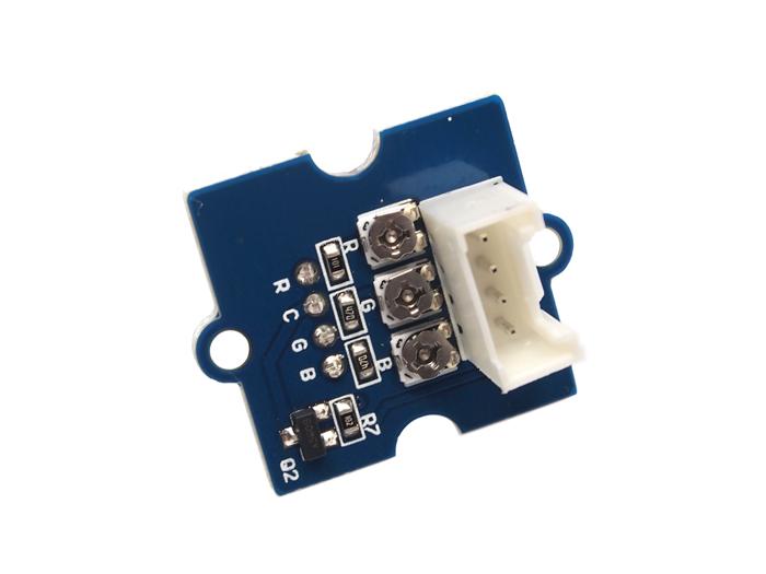
The three resistances RED, GREEN and BLUE of the module control the R, G and B channels respectively. By adjusting the three adjustable resistances, it can turn out variable color. The thing to notice, however, is that be gentle when turning the adjustable resistances.
The following sketch demonstrates a simple application of controlling its brightness. As the picture on the below indicates, the Variable Color LED is connected to digital port 9 of the Grove - Base Shield. The hardware installation is as follows:

- Copy and paste code below to a new Arduino sketch.
Demo code like:
int ledPin = 9;    // LED connected to digital pin 9

void setup()  {
    // nothing happens in setup
}

void loop()  {
    // fade in from min to max in increments of 5 points:
    for(int fadeValue = 0?; fadeValue <= 255; fadeValue +=5) {
        // sets the value (range from 0 to 255):
        analogWrite(ledPin, fadeValue);
        // wait for 30 milliseconds to see the dimming effect
        delay(30);
    }

    // fade out from max to min in increments of 5 points:
    for(int fadeValue = 255?; fadeValue >= 0; fadeValue -=5) {
        // sets the value (range from 0 to 255):
        analogWrite(ledPin, fadeValue);
        // wait for 30 milliseconds to see the dimming effect
        delay(30);
    }
}
- Upload the code.Adjust the three adjustable resistances, I am sure you will like it. Have a try!
Resources
| Arduino | Wio | BeagleBone | Raspberry Pi | LinkIt ONE |
|---|---|---|---|---|
Caution
The platforms mentioned above as supported is/are an indication of the module's hardware or theoritical compatibility. We only provide software library or code examples for Arduino platform in most cases. It is not possible to provide software library / demo code for all possible MCU platforms. Hence, users have to write their own software library.
Help us make it better
Welcome to the new documentation system of Seeed Studio. We have made a lot of progress comparing to the old wiki system and will continue to improve it to make it more user friendly and helpful. The improvement can't be done without your kindly feedback. If you have any suggestions or findings, you are most welcome to submit the amended version as our contributor via Github or give us suggestions in the survey below, it would be more appreciated if you could leave your email so that we can reply to you. Happy Hacking!