Grove - Slide Potentiometer
Introduction
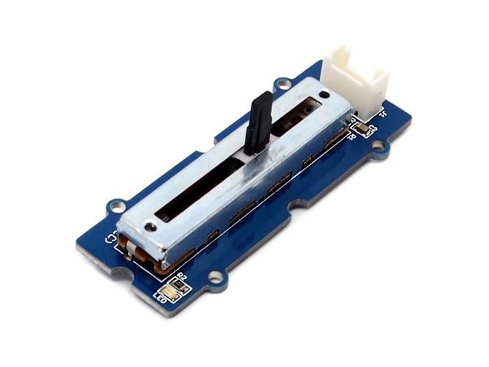
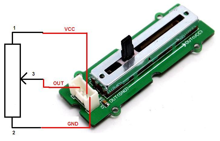
The Grove - Slide Potentiometer module incorporates a linear variable resistor with a maximum resistance of 10KΩ. When you move the slider from one side to the other, its output voltage will range from 0 V to the Vcc you apply. It connects to the other Grove modules through a standard 4-Pin Grove Cable. Three of the pins are connected to OUT (Pin 1), Vcc (Pin 3) and GND (Pin 4), while the fourth pin (Pin 2) is connected to a on-board green indicator LED. The LED is used to visually represent the resistance change on the potentiometer.

Features
- 30 mm long slide length
- Linear resistance taper
- Grove compatible
Tip
More details about Grove modules please refer to Grove System
Application Ideas
Here are some projects for your reference.
| Arduino BoomBox | Arduino BeatBox |
|---|---|
 |
 |
| Make it NOW! | Make it NOW! |
Specifications
| Item | Min | Typical | Max |
|---|---|---|---|
| Voltage (DC) | 3.3V | 5.0V | 30V |
| Current | - | - | 30mA |
| Dimension | 24mm x60mm | ||
| Net Weight | 8.6g | ||
| Rotational life | >15,000 cycles | ||
| Total resistance | 10KΩ | ||
| Stroke length | 30mm | ||
| Total resistance tolerance | +/- 20% | ||
Platforms Supported
Getting Started
As an Adjustable Resistor
As shown below, the Grove - Slide Potentiometer can be used as a simple slide potentiometer in any MCU controlled or stand-alone project.
Standalone
Follow these steps to build a sample Grove circuit using this module but without using any microcontroller board:
- Connect the slide potentiometer module to the input side of your circuit (to the left of the power module). On the output side of the circuit, you may use a range of User Interface modules (Grove - Red LED, Grove - LED String Light, Grove - Mini Fan, Grove - Buzzer, Grove - Recorder etc.)
- Power up the circuit when complete.
-
The slide potentiometer module can now be used to trigger an output. For example:
- When used in conjunction with a Grove - Red LED output module, observe that the brightness of the LED increases as you move the slider from GND to Vcc. At Vcc, the resistance of the potentiometer is minimum and the LED burns the brightest. The same behavior can be seen when the slide potentiometer is used with the Grove - LED String Light module - the more voltage you apply by taking the slider towards the Vcc mark, the brighter the LED lights would become.
- Similarly, you can use the slide potentiometer to vary the speed of your Grove - Mini Fan or the frequency with which your Grove - Buzzer module sounds
- The slide potentiometer can also be used as an ON/OFF switch for any circuit. Take the slider to the Vcc position to switch it ON and move it down to GND to switch OFF a circuit.
In terms of choosing a power module, you can use either the Grove - USB Power module or the Grove - DC Jack Power module for building standalone Grove circuits.
With Arduino
As a Voltage Divider
Follow these simple steps to make the slide potentiometer module function as a voltage divider:
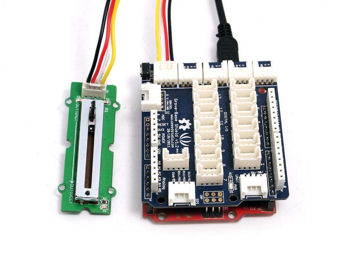
1.When using the module in conjunction with an Arduino or a Seeeduino, use the Grove - Base Shield and connect the Grove - Slide Potentiometer module to the shield using a designated Grove Interface (e.g. Analog Port 0 as shown below).
2.Connect the board to PC using USB cable.
3.Upload the following sample sketch.
int adcPin = A0; // select the input pin for the potentiometer
int ledPin = A1; // select the pin for the LED
int adcIn = 0;   // variable to store the value coming from the sensor
void setup()
{
    Serial.begin(9600); // init serial to 9600b/s
    pinMode(ledPin, OUTPUT); // set ledPin to OUTPUT
    Serial.println("Sliding Potentiometer Test Code!!");
}
void loop()
{
    // read the value from the sensor:
    adcIn = analogRead(adcPin);
    if(adcIn >= 500) digitalWrite(ledPin,HIGH);  // if adc in > 500, led light
    else digitalWrite(ledPin, LOW);
    Serial.println(adcIn);
    delay(100);
}
4.Open the serial monitor. You should see some data from ADC.
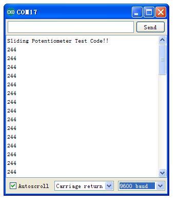
5.Move the lever back and forth. The serial data will change correspondingly. When the output resistance exceeds a certain preset value, the on-board indicator LED will also light up.
As an HID Device
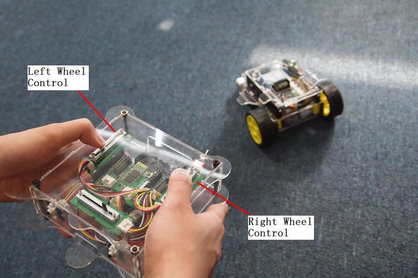
Slide Potentiometer can be an effective Human Interface Device (HID) and can be used, for example, in the radio controller of a Radio Controlled toy car. The picture below shows two Slide Potentiometers on the control panel - one to control the speed of the left wheel, and the other to control the speed of the right wheel of the toy car respectively. Now you can change the speeds of both motors and see the behavior. You will see that if you make the right wheel spin faster than the left wheel, the car will turn rightwards, and if you make the left wheel spin faster than the right wheel, the car will turn leftwards.
With Raspberry Pi
1.You should have got a raspberry pi and a grovepi or grovepi+.
2.You should have completed configuring the development enviroment, otherwise follow here.
3.Connection
- Plug the sensor to grovepi socket A0 by using a grove cable.
4.Navigate to the demos’ directory:
cd yourpath/GrovePi/Software/Python/
- To see the code
nano grove_slide_potentiometer.py # "Ctrl+x" to exit #
import time
import grovepi

# Connect the Grove Slide Potentiometer to analog port A0
# OUT,LED,VCC,GND
slide = 0   # pin 1 (yellow wire)

# The device has an onboard LED accessible as pin 2 on port A0
# OUT,LED,VCC,GND
led = 1     # pin 2 (white wire)

grovepi.pinMode(slide,"INPUT")
grovepi.pinMode(led,"OUTPUT")
time.sleep(1)

while True:
    try:
        # Read sensor value from potentiometer
        sensor_value = grovepi.analogRead(slide)

        # Illuminate onboard LED
        if sensor_value > 500:
            grovepi.digitalWrite(led,1)
        else:
            grovepi.digitalWrite(led,0)

        print "sensor_value =", sensor_value

    except IOError:
        print "Error"
5.Run the demo.
sudo python grove_slide_potentiometer.py
Resources
| Arduino | Wio | BeagleBone | Raspberry Pi | LinkIt ONE |
|---|---|---|---|---|
Caution
The platforms mentioned above as supported is/are an indication of the module's hardware or theoritical compatibility. We only provide software library or code examples for Arduino platform in most cases. It is not possible to provide software library / demo code for all possible MCU platforms. Hence, users have to write their own software library.
Help us make it better
Welcome to the new documentation system of Seeed Studio. We have made a lot of progress comparing to the old wiki system and will continue to improve it to make it more user friendly and helpful. The improvement can't be done without your kindly feedback. If you have any suggestions or findings, you are most welcome to submit the amended version as our contributor via Github or give us suggestions in the survey below, it would be more appreciated if you could leave your email so that we can reply to you. Happy Hacking!