Wio LTE Cat.1
Introduction
![]()
Wio Tracker (Wireless Input Output) is an open source gateway which enable faster IoT GPS solutions. It is Arduino and Grove compatible development boards that helps you track nearly any moving thing on the planet and then upload that data wirelessly. The Wio LTE is the LTE version of Wio Tracker, so now we’ve got 2 versions of Wio Tracker and the LTE (4G) version will make some differences.
There are three main updates comparing the Wio LTE to the 2G version. Firstly, from its name we know that the Wio LTE supports LTE (4G) communication which is much faster and popular than 2G. Secondly, the Wio LTE supports in total 4 different GNSS – GPS, Beidou, GLONSS and Galileo, the QZSS is also supported as bonus. With more GNSS support, positioning will be more accurate. Thirdly, the Wio LTE‘s MCU is upgraded to STM32, which is based on Cortex-M4, makes the Wio LTE 5 times faster than the 2G version. What’s more, the flash and RAM have also been raised to 1Mbytes and 192+4k bytes.
Apart from the three main updates, the LTE version is almost the same as the 2G version. If your project is using the 2G version, it would be very easy to update to the LTE version because we have prepared transplantable and expansible AT command library. The Arduino and Grove compatibility allows for quicker development through numerous libraries and a supportive community. The GPS library which will be available with the board is not just limited to Arduino – it can function just as well if you chose to develop in C/C++. With the onboard 6 Grove connections, developers can create any combination of our 180+ sensors and actuators to build project and solve any problem. Simplifying the prototyping and development phase is our goal.
The Wio LTE is well suited for outdoor projects where the device can connect to the GPS satellites and provide a real-time location of the item it is attached to. The LTE provides a wide bandwidth which allows much faster interaction between the user and device. If you are going to build projects like a bicycle sharing service, tracking pets or livestock, locating a vehicle, or even keeping track of a child, the Wio LTE is the best solution.
Warning
Please always plug 3.7V Lipo battery in case USB power supply is not sufficient.
| Product Name | How to Buy |
|---|---|
| Wio LTE JP Version |  |
| Wio LTE AU Version | |
| Wio LTE EU Version | |
| Wio LTE US Version | |
Version
| Product Version | Changes | Released Date |
|---|---|---|
| Wio Lte V1.0 | Initial | Jul 24, 2017 |
| Wio Lte V1.1 |
Optimizing production methods | Oct 18, 2017 |
Features
- Low-cost, low-power LTE connectivity optimized for broad- band IoT applications
- Worldwide LTE and UMTS/HSPA+
- Embedded power management unit (PMU) featuring ultra-low deep-sleep current consumption
- GPS/BeiDou/GLONASS/Galileo and QZSS
- Transplantable and expansible AT Command Library for Wio Tracker
- Arduino IDE compatible
- 6 Grove Connectors
- Nano SIM and TF card 2 in 1 socket
Specification
| Item | Function | Value |
|---|---|---|
| Microcontroller | Processor | STM32F405RG, ARM 32-bit Cortex-M4, 168MHZ |
| Flash Memory | 1MB | |
| SRAM | 192+4KB | |
| Operating Voltage | 3.3V | |
| DC Current per I/O Pin | 7 mA | |
| LTE | LTE Cat.1 | AT Command: 3GPP TS27.007 and enhanced AT Commands |
| Data | LTE-FDD Max 10Mbps(DL) Max 5Mbps (UL) | |
| Protocol: TCP/UDP/PPP/FTP/HTTP/NTP/PING/QMI/HTTPS/SMTP/MMS/FTPS/SMTPS/SSL | ||
| SMS | Peer to Peer Message, SMS broadcast, Text and PDU mode | |
| Audio | Echo cancellation, Noise elimination | |
| GNSS | System | GPS/BeiDou/GLONASS/Galileo/QZSS |
| Precision | <2.5 m CEP | |
| Peripheral | Grove | 2 x Digital Port |
| 2 x Analog Port | ||
| 1 x UART | ||
| 1 x I2C | ||
| Antenna | 2 x LTE Antenna | |
| 1 x GPS Antenna | ||
| Others | USB: Power supply and upload program | |
| JST 1.0 connecter for battery | ||
| 3.5mm Audio Jack | ||
| MCU Reset Button, MCU Boot(DFU) Button,EC21 Power Button | ||
| 1 x User RGB LED SK6812 | ||
| Nano SIM and TF card 2 in 1 socket | ||
| Size | Length | 54.7mm |
| Width | 48.2mm | |
| Weight | 18g |
Power Consumption
| Status | Current | Voltage |
|---|---|---|
| Normal boot(boot moment) | 700mA | 5V |
| After boot(IDLE mode) | 300mA | 5V |
| After the boot, the normal communication status (network transmission function) | 600mA or so, the peak reaches 2A | 5V |
| Call and SMS(signal better) | 100-300mA | 5V |
| Deep sleep mode, turn off all functions, require external wake-up (wake only by Reset) | 300uA | 4.2V |
| MCU Deep Sleep mode, wake-up pin connected to module, wake-up via module | over 300uA (requires testing) | 4.2V |
Application Ideas
- Pedometer
- Smart ski
- Smart two-wheeler
- Sharing bicycle
- Pet tracking machine
- Children location watch
- Smart watch
- Transportation location system
- Vehicle location system
- Property safety
Tip
Use Grove modules to expand your application. There are 6 Grove connects on board. If this is your first time to hear about Grove, please put had on Grove System for more details. In brief, Groves is hundreds of sensor that in standard style, which is consist of sensors, actuators, displays as well as communication.
Hardware Overview
![]()
![]()
Tip
If you want to use the on-board Grove connector, please use digitalWrite(B10, HIGH) to open 3V3_B. except D38 power on by default. Otherwise you can’t provide power to Grove modules.
EC21 Module
EC21 contains 9 variants: EC21-E, EC21-A, EC21-V, EC21-AUT, EC21-AUV, EC21-AU, EC21-KL, EC21-J and EC21-CEL. This makes it backward-compatible with existing EDGE and GSM/GPRS networks, ensuring that it can easily migrate from LTE to 2G or 3G networks.
And EC21-A is what we are using in WIO Tracker - LTE, which supports AT&T and T-mobile sim card. If you want to customize EC21 Module for other region, feel free to email us: fae@seeed.cc
| Frequency | EC21-E | EC21-A | EC21-V | EC21-AUT | |
|---|---|---|---|---|---|
| LTE | FDD-LTE | B1/ B3/ B5/ B7/ B8/ B20 | B2/ B4/ B12 | B4/ B13 | B1/ B3/ B5/ B7/ B28 |
| TDD-LTE | |||||
| 3G | WCDMA | B1/ B5/ B8 | B2/ B4/ B5 | B1/ B5 | |
| GSM/EDGE | B3/ B8 | ||||
| Embedded GNSS | Optional | Optional | Optional | Optional | |
| Wi-Fi Interface | Y | Y | Y | Y | |
| Region | EMEA, Korea, Thailand, India | North America | North America | Australia | |
| Certification | CE/ GCF/ Vodafone | FCC/ PTCRB/ AT&T/ IC/ ROGERS | FCC/ GCF/ Verizon | RCM/ Telstra | |
| Frequency | EC21-AUV | EC21-AU | EC21-KL | EC21-J | EC20-CEL | |
|---|---|---|---|---|---|---|
| LTE | FDD-LTE | B1/ B3/ B5/ B8/ B28 | B1/ B2①/ B3/ B4/ B5/ B7/ B8/ B28 | B1/ B3/ B5/ B7/ B8 | B1/ B3/ B8/ B18/ B19/ B26 | B1/ B3/ B5 |
| TDD-LTE | B40 | |||||
| 3G | WCDMA | B1/ B5/ B8 | B1/ B2/ B5/ B8 | |||
| GSM/EDGE | Quad-band | |||||
| Embedded GNSS | N |
Optional |
N |
N |
N | |
| Wi-Fi Interface | Y | Y | Y | Y | Y | |
| Region | Vodafone Australia | South America, ANZ, Taiwan | Korea | Japan | China Telecom | |
| Certification | RCM | RCM/ Anatel/ NCC | KC/ SKT/KT*/ LGU+* | JATE/ TELEC/ DOCOMO* | CCC/ SRRC/ NAL | |
Getting Started
Install USB driver
-
Windows Users: Most versions of Windows won’t automatically load the built-in driver for USB com ports. You’ll have to download ST’s USB driver:
-
Non-Windows XP Users download version 1.4.0 drivers. Unzip the file, run the executable, and then go to C:\Program Files (x86)\STMicroelectronics\Software\Virtual comport driver in Windows Explorer and double-click either dpinst_amd64.exe for 64 bit systems, or dpinst_x86.exe for 32 bit.
-
Windows XP Users download version 1.3.1 drivers. Unzip the file, run VCP_V1.3.1_Setup.exe, and then go to C:\Program Files\STMicroelectronics\Software\Virtual comport driver in Windows Explorer and double-click the executable.
-
-
Linux users to ensure that you have the correct permissions to connect as a normal user you’ll need to copy the file 45-espruino.rules to /etc/udev/rules.d, reload rules with udevadm control –reload-rules, and ensure your user is in the plugdev group (you can check by typing groups). You add it by typing sudo adduser $USER plugdev and then logging out and back in. Arch Linux users need to add their user to uucp and lock groups instead.
-
Mac OS X and Chromebook Users: The board will just plug in and work, without drivers!
Change DFU driver
For windows users: Press and hold BOOT button and connect to computer you will see STM32 Device in DFU Mode at device manager, this says that you need to use zadig_xx.exe to change DFU driver from STTub30 to WinUSB as bellow.
Update Firmware
- Step 1: Download WioLTE firmware v1.93 or look for espruino_xxx_Wio_LTE.bin here (v1.94 didn’t support SD card, please download v1.93).
- Step 2: Install dfu-util, add dfu-util to PATH or Environment Variables, so that we can use it directlly in command line.
- Step 3: Press and hold BOOT0 button before connect to computer, release after connect.
- Step 4: The Wio LTE board will access DFU mode.
- Step 5: In command line windows type dfu-util -d 0483:df11 -c 1 -i 0 -a 0 -s 0x08000000 -D xxx.bin. For windows, Please enter the full path of the bin file.
![]()

Play with Javascript
Thanks to G.Williams for providing Espruino the Javascript interpreter, so that we can prototype things with Javascript.
Install Espruino web IDE
- Step 1: Install Chrome Web Browser
- Step 2: Click here to get Espruino Web IDE
- Step 3: Run Espruino Web IDE from chrome’s home screen or the App Launcher (type chrome://apps* at the address bar)
![]()
How to use Espruino Web IDE
-
Step 1: Connect the Wio LTE board to computer using a micro USB cable. On device manager you can see a new COM Port device, on MacOS it is STM32 Virtual ComPort, on windows it is STMicroelectronic Virtual COM Port.
-
Step 2: On the Web IDE click the left top icon, choose Espruino board in the select box.
![]()
- Step 3: To learn more about the IDE, please click help and then tour as below.
![]()
How to load modules
In Espruino, Modules are pieces of pre-written code (libraries) that perform common tasks, such as interfacing to different bits of hardware.
They can currently be used in a few different ways:
Espruino Web IDE
If you’re using the Espruino Web IDE, simply write require(“modulename”) on the right-hand side - as you would have seen in the reference pages. When you click the Send to Espruino button, the Web IDE will automatically look online for minified versions of the modules you need, download them, and load them onto the board. You don’t need an SD card or an internet connection to the Espruino board itself.
Load Module - the default mechanism
If you are using the Web IDE as is, the modules will be loaded from http://www.espruino.com/modules/. This URL can be changed in Web IDE settings.
To save space, most modules are provided as a minified version and the Web IDE tries to load minified versions first with default configuration.
For example, using require(“ADNS5050”); will make the Web IDE loading the minified module from http://www.espruino.com/modules/ADNS5050.min.js.
Load Module from Github
For now, as you can type a URL into require, you can actually just pull a module right off GitHub:
require("https://github.com/espruino/EspruinoDocs/blob/master/devices/PCD8544.js");
You can even look at the history of something on GitHub, and can then require a specific version of that file with:
require("https://github.com/espruino/EspruinoDocs/blob/d4996cb3179abe260c030ed02bcb0d2384db6bbd/devices/PCD8544.js");
The URL comes from clicking <> by the commit you were interested in.
Load Module from NPM
If you activate this option in Web IDE, you can load modules from the NPM repository. Right now it:
- only loads the latest version there.
- only works if the module contains a single file.
- can cause some confusion with Espruino’s modules, for instance clock.
For example using require(“async”); will make the Web IDE loading the tar.gz file (with automatic extraction) of the module from http://registry.npmjs.org/async.
Load Module from local folder
If you are using a local project folder, the Web IDE will automatically create an empty modules folder inside. Put a module there and you can load it with require(“myCustomModule”);.
![]()
With default Web IDE configuration, it will look for modules following this order:
- local minified
- online minified
- local normal
- online normal
If your own module has the same name as one of the existing ones, the Web IDE will use the minified version from online first.
If you need it anyway, you can provide a local minified version or you can change the Web IDE configuration from .min.js|.js to .js|.min.js or even myCustomModule.js|.min.js|.js to get it working.
Stand-alone Espruino
If you have an Espruino with an SD card (but you’re not using the Web IDE), you can copy the modules you need into a directory called ‘node_modules’ on the SD card. Now, whenever you write require(“modulename”) the module will be used.
Internet-enabled Espruino
Right now there isn’t a way to make Espruino automatically load a module from the internet when required without the Web IDE. This may be added in the future, but the fact that require is synchronous while network connections are asynchronous makes this difficult to do reliably until yield is added into the interpreter.
Until then, the following asyncronous code will dynamically load a module from the internet on demand.
function loadModule(moduleName, callback) {
  require("http").get("http://www.espruino.com/modules/"+moduleName+".js", function(res) {
    var contents = "";
    res.on('data', function(data) { contents += data; });
    res.on('close', function() {
      Modules.addCached(moduleName, contents);
      if (callback) callback();
    });
  }).on('error', function(e) {
    console.log("ERROR", e);
  });
}
Play with Onboard RGB LED
- Step 1. Config the R, G, B numbers, the arrange is 0~255.
- Step 2. Copy the code to IDE and upload to board.
- Step 3. The on board RBG LED will be turned on.
WioLTE.setLEDPower(true);
WioLTE.LED(r,g,b); // please modify the RGB to values with range 0..255)
// Dynamic colors show
WioLTE.setLEDPower(true);

var rgb = new Uint8ClampedArray(3);
var pos = 0;
function getPattern() {
  pos++;
  for (var i=0;i<rgb.length;) {
    rgb[i++] = (1 + Math.sin((i+pos)*0.1324)) * 10;
    rgb[i++] = (1 + Math.sin((i+pos)*0.1654)) * 10;
    rgb[i++] = (1 + Math.sin((i+pos)*0.1)) * 10;
  }
  return rgb;
}
setInterval(function() {
  var color = getPattern();
  WioLTE.LED(color[0], color[1], color[2]);
}, 100);
Play with SD Card
Note: espruino firmware v1.94 is not support SD card drive, please use v1.93 or v1.96(May not released) - Step 1. Plug a micro SD card to the card slot - Step 2. Copy the code to Espruino IDE and upload it.
var fs = require('fs');

// Init SDCard
WioLTE.init;

// List files
console.log('List files on root path:\r\n', fs.readdirSync());
// Write file
fs.writeFileSync("hello.txt", "Hello World");
// read file
console.log(fs.readFileSync("hello.txt"));
// append file
fs.appendFileSync("hello.txt", "!!!");
// read again
console.log(fs.readFileSync("hello.txt"));
Play with Grove Module
Play with Digital Ports
Grove-Button (Input)
- Step 1. Conenct Grove-Button to Wio LTE D38 port.
- Step 2. Copy the code to IDE and upload to board.
- Step 3. We will see the “Pressed” when we press the button. Or else, we will see “Released” printed on screen.
WioLTE.setGrovePower(true);
var button = new (require("GroveButton"))(WioLTE.D38, function(e) {
  if (e.state) console.log("Pressed");
  else console.log("Released");
});
Grove-Ralay (Output)
- Step 1. Conenct Grove-Ralay to Wio LTE D38 port.
- Step 2. Copy the code to IDE and upload to board.
- Step 3. We will hear the Relay switch and see the “Done” printed on screen.
WioLTE.setGrovePower(true);
var relay = new (require('GroveRelay'))(WioLTE.D38);
setInterval(function() {
  relay.off();
  relay.pulse(1000, function() {
    console.log("Done!");
});
}, 2000);
Play with Analog Ports
Grove-Light Sensor
- Step 1. Conenct Grove-Light Sensor to Wio LTE A4 port.
- Step 2. Copy the code to IDE and upload to board.
- Step 3. We will see the numbers printed on screen.
WioLTE.setGrovePower(true);
var light = new (require('GroveLightSensor'))(WioLTE.A4);
setInterval(function() {
  console.log(r.read());
}, 500);
Play with UART Ports
Grove-GPS
- Step 1. Conenct Grove-GPS to Wio LTE UART port.
- Step 2. Copy the code to IDE and upload to board.
WioLTE.setGrovePower(true);
Serial1.setup(9600,{tx:WioLTE.UART[1],rx:WioLTE.UART[0]});
var gps = new (require('GPS')).connect(Serial1, function(data) {
  console.log(data);
});
- Step 3. We will see time, lat, lon, satellites and altitude info printed on screen as below.
{  "time": "09:35:02", "lat": 30.69766, "lon": 104.05367833333, "fix": 1, "satellites": 6, "altitude": 537.2 }
{  "time": "09:35:03", "lat": 30.69765166666, "lon": 104.05366166666, "fix": 1, "satellites": 6, "altitude": 537.2 }
{  "time": "09:35:04", "lat": 30.69765, "lon": 104.05363833333, "fix": 1, "satellites": 6, "altitude": 537.1 }
Play with I2C Ports
Grove 3-Axis Digital Accerlerometer(±16g)
- Step 1. Conenct Grove 3-Axis Digital Accerlerometer(±16g) to Wio LTE I2C port.
- Step 2. Copy the code to IDE and upload to board.
WioLTE.setGrovePower(true);
I2C1.setup({scl:WioLTE.I2C[0], sda:WioLTE.I2C[1]});
var accel = require("ADXL345").connect(I2C1,0,0);
accel.measure(true);
setInterval(function(){
  console.log(accel.read());
},2000);
- Step 3. We will see x, y and z info printed on screen as below.
{ "x": -0.05859375, "y": -0.46484375, "z": 0.76953125 }
{ "x": -0.0546875, "y": -0.46484375, "z": 0.765625 }
{ "x": -0.0546875, "y": -0.46875, "z": 0.7578125 }
{ "x": -0.05078125, "y": -0.47265625, "z": 0.765625 }
{ "x": -0.0546875, "y": -0.46484375, "z": 0.77734375 }
{ "x": -0.0546875, "y": -0.46875, "z": 0.765625 }
{ "x": -0.0546875, "y": -0.46875, "z": 0.765625 }
{ "x": -0.05078125, "y": -0.47265625, "z": 0.765625 }
Play with Onboard LTE and GPS
When require modules the Espruino Web IDE will automaticlly search modules at the modules repository. To use LTE and GPS functionalities, you need to require the wiolte module with require(‘wiolte’).
Play with Send and Receive SMS
- Step 1. Plug the Nano SIM card into Nano SIM slot, near PCB board side.
- Step 2. Change the phone number and info.
- Step 3. Copy the code to IDE and upload to board.
- Step 4. The phone number owner will receive the message.
- Step 5. If someone sends the message to you, it will be printed on the screen as well.
digitalWrite(B2, 1);
var board;
var APN = "CMAPN";
var USERNAME = "";
var PASSWORD = "";

function wiolteStart(debug_quectel, debug_at) {
  debug_quectel = debug_quectel || false;
  debug_at = debug_at || false;

  board = require('wiolte').connect(function(err) {
    console.log("connectCB entered...");
    if (err) throw err;
    setTimeout(doConnect,3000);
  });

  board.debug(debug_quectel, debug_at);

}

function doConnect() {
  board.connect(APN, USERNAME, PASSWORD, function(err) {
    console.log("connectCB entered...");
    if (err) throw err;
    board.getIP(print);

    // work after connected
    setTimeout(onConnected, 5000);

  });
}

function onConnected(){
  // Send the SMS message, please change the phone number
  board.SMS.send("185XXX26402", "What is the story?",function(err) {
    console.log(err);
  });

  //Receive SMS coming
  board.on('message', function(id){
    board.SMS.read(id, function(d, sms){
      if(d !== "OK") throw new Error(d);
      console.log('SMS from:', sms.oaddr);
      console.log(':', sms.text);
    });
  });

}

wiolteStart();
Play with Call Out
- Step 1. Plug the Nano SIM card into Nano SIM slot, near PCB board side.
- Step 2. Plug the Headphone into audio port.
- Step 3. Change the phone number.
- Step 4. Copy the code to IDE and upload to board.
- Step 5. The phone number owner will receive the phone call.
digitalWrite(B2, 1);
var board;
var APN = "CMAPN";
var USERNAME = "";
var PASSWORD = "";

function wiolteStart(debug_quectel, debug_at) {
  debug_quectel = debug_quectel || false;
  debug_at = debug_at || false;

  board = require('wiolte').connect(function(err) {
    console.log("connectCB entered...");
    if (err) throw err;
    setTimeout(doConnect,3000);
  });

  board.debug(debug_quectel, debug_at);

}

function doConnect() {
  board.connect(APN, USERNAME, PASSWORD, function(err) {
    console.log("connectCB entered...");
    if (err) throw err;
    board.getIP(print);

    // work after connected
    setTimeout(onConnected, 5000);

  });
}

//please change the phone number
function onConnected(){
  board.Call.call("185XXX26402");
}

wiolteStart();
- Step 5. If we see “Disconnected” during phone call as below, the root cause is that power supply is not sufficient. Please connect the battery or connect to a hub with sufficiant power.
_____                 _
|   __|___ ___ ___ _ _|_|___ ___
|   __|_ -| . |  _| | | |   | . |
|_____|___|  _|_| |___|_|_|_|___|
         |_| http://espruino.com
1v94 Copyright 2016 G.Williams
Espruino is Open Source. Our work is supported
only by sales of official boards and donations:
http://espruino.com/Donate
>
=undefined
AT passedd
PS attachment succeeded
currently selected operator :+COPS: 0,0,"CHINA MOBILE",7
connectCB entered...
PDP context successfully activated
connectCB entered...
null 10.114.177.248
IP address allocated, modem is ready to use
>
Disconnected
Play with Answer Call
- Step 1. Plug the Nano SIM card into Nano SIM slot, near PCB board side.
- Step 2. Plug the Headphone into audio port.
- Step 3. Copy the code to IDE and upload to board.
- Step 4. It will pick up the phone call automatically.
digitalWrite(B2, 1);
var board;
var APN = "CMNET";
var USERNAME = "";
var PASSWORD = "";

function wiolteStart(debug_quectel, debug_at) {
  debug_quectel = debug_quectel || false;
  debug_at = debug_at || false;

  board = require('wiolte').connect(function(err) {
    console.log("connectCB entered...");

    if (err) throw err;
    setTimeout(doConnect,3000);
  });

  board.debug(debug_quectel, debug_at);

}

function doConnect() {
  board.connect(APN, USERNAME, PASSWORD, function(err) {
    console.log("connectCB entered...");
    if (err) throw err;
    board.getIP(print);

    // work after connected
    setTimeout(onConnected, 5000);

  });
}

function onConnected(){
  // Handle call coming
  board.Call.handleRing(true);
  board.on('RING', function(){
    console.log("RING");
    board.Call.answer(function(err){
      print(err);
    });
  });
}

wiolteStart();
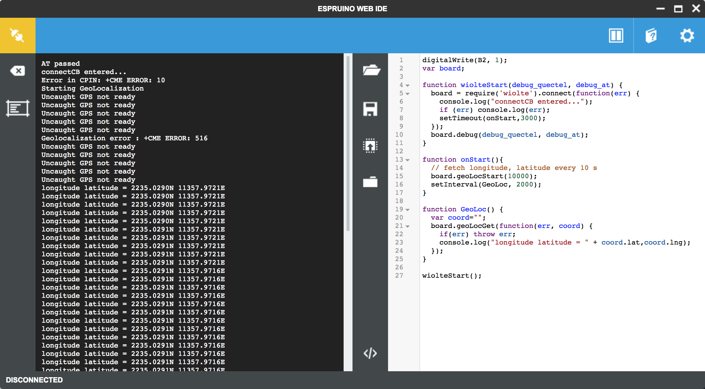
Play with GPS Location
- Step 1. Plug the Nano SIM card into Nano SIM slot, near PCB board side.
- Step 2. Copy the code to IDE and upload to board.
- Step 3. After Geolocalization error : +CME ERROR: 516 stop logging, type Geoloc() to show GPS infomation.
digitalWrite(B2, 1);
var board;

function wiolteStart(debug_quectel, debug_at) {
  board = require('wiolte').connect(function(err) {
    console.log("connectCB entered...");
    if (err) console.log(err);
    setTimeout(onStart,3000);
  });
  board.debug(debug_quectel, debug_at);
}

function onStart(){
  // fetch longitude, latitude every 10 s
  board.geoLocStart(10000);
  setInterval(GeoLoc, 2000);
}

function GeoLoc() {
  var coord="";
  board.geoLocGet(function(err, coord) {
    if(err) throw err;
    console.log("longitude latitude = " + coord.lat,coord.lng);
  });
}

wiolteStart();
Play with Get Html Page
- Step 1. Plug the Nano SIM card into Nano SIM slot, near PCB board side.
- Step 2. Copy the code to IDE and upload to board.
digitalWrite(B2, 1);
var board;
var APN = "CMNET";
var USERNAME = "";
var PASSWORD = "";

function wiolteStart(debug_quectel, debug_at) {
  debug_quectel = debug_quectel || false;
  debug_at = debug_at || false;

  board = require('wiolte').connect(function(err) {
    console.log("connectCB entered...");
    if (err) throw err;
    setTimeout(doConnect,3000);
  });

  board.debug(debug_quectel, debug_at);

}

function doConnect() {
  board.connect(APN, USERNAME, PASSWORD, function(err) {
    console.log("connectCB entered...");

    if (err) throw err;
    board.getIP(print);

    // work after connected
    setTimeout(onConnected, 5000);

  });
}

function onConnected(){

  GetHtmlPage("http://www.pur3.co.uk/hello.txt");
}

function GetHtmlPage(html_page){
  require("http").get(html_page, function(res) {
    var contents = "";

    console.log("Response: ",res);

    res.on('data', function(d) {
      contents += d;
    });

    res.on('close', function(d) {
        console.log("Connection closed");
        console.log("full page content ---> \r\n"+contents);
    });
  });
}


wiolteStart();
- Step 3. We will see info printed on screen.
_____                 _
|   __|___ ___ ___ _ _|_|___ ___
|   __|_ -| . |  _| | | |   | . |
|_____|___|  _|_| |___|_|_|_|___|
         |_| http://espruino.com
1v94 Copyright 2016 G.Williams
Espruino is Open Source. Our work is supported
only by sales of official boards and donations:
http://espruino.com/Donate
>
=undefined
AT passed
PS attachment succeeded
currently selected operator :+COPS: 0,0,"CHINA MOBILE",7
connectCB entered...
PDP context successfully activated
connectCB entered...
null 10.162.62.37
IP address allocated, modem is ready to use
Response:  httpCRs {
 "headers": {
   "Date": "Thu, 14 Dec 2017 10:25:57 GMT",
   "Server": "Apache/2.4.18 (Ubuntu)",
   "Last-Modified": "Fri, 15 Nov 2013 15:42:26 GMT",
   "ETag": "\"d-4eb390b887c80\"",
   "Accept-Ranges": "bytes",
   "Content-Length": "13",
   "Connection": "close",
   "Content-Type": "text/plain"
  },
 "httpVersion": "1.1",
 "statusCode": "200",
 "statusMessage": "OK"
}
Connection closed
full page content --->
Hello World!
Javascript APIs
For more info, please refer to Wio_LTE_Module
- debug(boolean, boolean) - choose debug level
- reset(callback) - Reset LTE
- init(callback) - Initialise LTE
- getVersion(callback) - returns LTE firmware version
- connect(apn, username, password, callback) - Connect to mobile network
- getVersion(callback) - returns current version
- getIP(callback) - Get current IP address
- geoLocStart(period_in_milliseconds) - Start getting geolocation data
- geoLocStop() - Stop getting geolocation data
- geoLocGet(callback) - Get last location
- geoLocConvert(callback(err,latlong)) - Get last location as latitude/longitude
- board.SMS - SMS functionality with init/read/send/list/delete functions based on the [[ATSMS]] module
- board.Call, with:
- call(number, callback)
- answer(callback)
- hangup(callback)
- handleRing(boolean) - if trie, will call any function added with board.on(‘RING’, …)
- sleep(callback) - LTE modem get into sleep mode, it can save about 100mA
- wake(callback) - LTE modem wake up from sleep mode
Play with Arduino
Software Configuration
- Step 1. Install Arduino IDE, recommand IDE version upon 1.8.0.
- Step 2. Follow How to Add Seeed boards to Arduino IDE to add Wio_LTE into arduino board manager.
- Step 3. Download the Wio_LTE Library from Github.
- Step 4. Refer How to install library to install library for Arduino.
Play with SMS Send
- Step 1. Plug the Nano SIM card into Nano SIM slot, near PCB board side.
- Step 2. Select File–> Examples–>Wio_LTE_Arduino_Library–>SMSSend sketch.
- Step 3. Change the phone number and info.
- Step 4. Press and hold BOOT button at back side of the Wio LTE and plug the USB to PC.
- Step 5. We will see STM BOOLARDER in device manager.
- Step 6. Select Tools–>Boards–>Wio_Tracker_LTE.
- Step 7. Keep COM Port blank.
- Step 8. Select Sketch–>Upload to upload the code to Wio_LTE.
- Step 9. Press RST button to enable the COM port.
#include "wio_tracker.h"

char message[128] = "Hello from Wio Traker!";

WioTracker wio = WioTracker();

void setup() {
  wio.Power_On();
  SerialUSB.println("Power On!");

  if(!wio.waitForNetworkRegister())
  {
    SerialUSB.println("Network error!");
    return;
  } else {
    SerialUSB.println("Network ready!");
  }

  // Change xxxxxxxxxxx to your test phone number
  if(wio.sendSMS("185XXX26402", message))
  {
    SerialUSB.println("Send OK!");
  }
  else
  {
    SerialUSB.println("Send Error!");
  }

}

void loop() {
  AT_bypass();
}
- Step 10.Use COM monitor tools to print the serial message. Please do not use Arduino IDE COM monitor! That may cause the next time downloading fail, bute reopen Arduino IDE can recover that issue.
- Step 11. The phone number owner will receive the message.
Power On!


Network ready!


Send OK!
Play with SMS Read
- Step 1. Plug the Nano SIM card into Nano SIM slot, near PCB board side.
- Step 2. Select File–> Examples–>Wio_LTE_Arduino_Library–>SMSRead sketch.
- Step 3. Press and hold BOOT button at back side of the Wio LTE and plug the USB to PC.
- Step 4. We will see STM BOOLARDER in device manager.
- Step 5. Select Tools–>Boards–>Wio_Tracker_LTE.
- Step 6. Keep COM Port blank.
- Step 7. Select Sketch–>Upload to upload the code to Wio_LTE.
- Step 8. Press RST button to enable the COM port.
#include "wiowio_trackerlte.h"

uint16_t newSMSNumber = -1;
char message[128];
char phone[32];
char dateTime[32];


WioTracker wio = WioTracker();

void setup() {
  wio.Power_On();
  SerialUSB.println("Power On!");
  SerialUSB.println("Wait for network registered...");

  if(!wio.waitForNetworkRegister())
  {
    SerialUSB.println("Network error!");
    return;
  } else {
    SerialUSB.println("Network ready!");
  }
  wio.readAllRecUnreadSMS();  // Set all "REC UNREAD SMS" to "REC READ SMS"
}

void loop() {
  int id = wio.detectRecUnreadSMS();
  if(-1 != id){
    newSMSNumber = id;
    wio.readSMS(newSMSNumber, message, 128, phone, dateTime);
    SerialUSB.println("++++++++++++++ Start +++++++++++++++++");
    SerialUSB.print("From: ");
    SerialUSB.println(phone);
    SerialUSB.print("Date: ");
    SerialUSB.println(dateTime);
    SerialUSB.println(message);
    SerialUSB.println("++++++++++++++++ End +++++++++++++++");
  } else {
    SerialUSB.println("Waiting for new SMS!");
  }

  delay(1000);
}
- Step 9.Use COM monitor tools to print the serial message. Please do not use Arduino IDE COM monitor! That may cause the next time downloading fail, bute reopen Arduino IDE can recover that issue.
- Step 10. Open serial monitor, when seeing Waitting for new SMS!, send message to the board, the new message will display soon with phone number, time, content.
Power On!
Wait for network registered...


Network ready!


Waiting for new SMS!
Waiting for new SMS!
Waiting for new SMS!

++++++++++++++ Start +++++++++++++++++
From: 1375002xxxx
Date: 17/12/20,17:40:38+32
Hello tracker
++++++++++++++++ End +++++++++++++++
Waiting for new SMS!
Waiting for new SMS!
Play with GPS
- Step 1. Plug the Nano SIM card into Nano SIM slot, near PCB board side.
- Step 2. Select File–> Examples–>Wio_LTE_Arduino_Library–>GNNS–>GNSS_Show_Coordinate sketch.
- Step 3. Press and hold BOOT button at back side of the Wio LTE and plug the USB to PC.
- Step 4. We will see STM BOOLARDER in device manager.
- Step 5. Select Tools–>Boards–>Wio_Tracker_LTE.
- Step 6. Keep COM Port blank.
- Step 7. Select Sketch–>Upload to upload the code to Wio_LTE.
- Step 8. Press RST button to enable the COM port.
#include "gnss.h"


GNSS gnss = GNSS();

void setup() {
  gnss.Power_On();
  while(false == gnss.Check_If_Power_On()){
    SerialUSB.println("Waitting for module to alvie...");
    delay(1000);
  }
  SerialUSB.println("\n\rPower On!");

  if(!(gnss.open_GNSS())){
    SerialUSB.println("\n\rGNSS init failed!");
    return;
  }

  SerialUSB.println("Open GNSS OK.");
  delay(2000);
}

void loop() {
  if(gnss.getCoordinate()){
    SerialUSB.println();
    SerialUSB.print("GNSS: \r\n");

    // Output double type
    SerialUSB.print("Data type in double: ");
    SerialUSB.print(gnss.longitude, 6);
    SerialUSB.print(",");
    SerialUSB.println(gnss.latitude, 6);

    // Output char* type
    SerialUSB.print("Data type in string: ");
    SerialUSB.print(gnss.str_longitude);
    SerialUSB.print(",");
    SerialUSB.println(gnss.str_latitude);
  } else{
    SerialUSB.print("...");
  }
}
- Step 9.Use COM monitor tools to print the serial message. Please do not use Arduino IDE COM monitor! That may cause the next time downloading fail, bute reopen Arduino IDE can recover that issue.
- Step 10. We will see lat, lon info printed on screen.
Waitting for module to alvie...
Waitting for module to alvie...
Waitting for module to alvie...

RDY
AT

OK


Power On!


Open GNSS OK.
.................................
GNSS:
Data type in double: 113.966255,22.583820
Data type in string: 113.966255,22.583819

GNSS:
Data type in double: 113.966248,22.583818
Data type in string: 113.966248,22.583818

GNSS:
Data type in double: 113.966248,22.583817
Data type in string: 113.966248,22.583816

GNSS:
Data type in double: 113.966248,22.583820
Data type in string: 113.966248,22.583819
Play with GPS in NMEA mode
- Step 1. Plug the Nano SIM card into Nano SIM slot, near PCB board side.
- Step 2. Select File–> Examples–>Wio_LTE_Arduino_Library–>GNNS–>GNSS_NMEA sketch.
- Step 3. Press and hold BOOT button at back side of the Wio LTE and plug the USB to PC.
- Step 4. We will see STM BOOLARDER in device manager.
- Step 5. Select Tools–>Boards–>Wio_Tracker_LTE.
- Step 6. Keep COM Port blank.
- Step 7. Select Sketch–>Upload to upload the code to Wio_LTE.
- Step 8. Press RST button to enable the COM port.
#include "gnss.h"


char nmea_sentence[192];
char nmea_GSV_sentence[512];
GNSS gnss = GNSS();

void setup() {
  gnss.Power_On();
  while(false == gnss.Check_If_Power_On()){
    SerialUSB.println("Waitting for module to alvie...");
    delay(1000);
  }
  SerialUSB.println("\n\rPower On!");

  if(!(gnss.open_GNSS())){
    SerialUSB.println("\n\rGNSS init failed!");
    return;
  }
  SerialUSB.println("Open GNSS OK.");
  gnss.enable_NMEA_mode();  // Set output sentence in NMEA mode
}

void loop() {
  clean_buffer(nmea_sentence, 192);
  gnss.read_NMEA(GGA, nmea_sentence);
  SerialUSB.print(nmea_sentence);

  clean_buffer(nmea_sentence, 192);
  gnss.read_NMEA(RMC, nmea_sentence);
  SerialUSB.print(nmea_sentence);

  clean_buffer(nmea_sentence, 192);
  gnss.read_NMEA(GSA, nmea_sentence);
  SerialUSB.print(nmea_sentence);

  clean_buffer(nmea_sentence, 192);
  gnss.read_NMEA(VTG, nmea_sentence);
  SerialUSB.print(nmea_sentence);

  clean_buffer(nmea_GSV_sentence, 512);
  gnss.read_NMEA_GSV(nmea_sentence);
  SerialUSB.print(nmea_sentence);

  SerialUSB.println("\r\n");

  delay(1000);
}
- Step 9.Use COM monitor tools to print the serial message. Please do not use Arduino IDE COM monitor! That may cause the next time downloading fail, bute reopen Arduino IDE can recover that issue.
- Step 10. We will see below logs.
Waitting for module to alvie...
Waitting for module to alvie...
Waitting for module to alvie...
Waitting for module to alvie...


Power On!


Open GNSS OK.

$GPRMC,,V,,,,,,,,,,N*53
$GPGSA,A,1,,,,,,,,,,,,,,,*1E
$GPVTG,,T,,M,,N,,K,N*2C
$GPGSV,3,1,12,16,60,324,40,27,54,171,40,03,19,253,,08,21,198,*7B
$GPGSV,3,2,12,09,02,322,,14,32,147,,21,04,080,,22,17,233,*7E
$GPGSV,3,3,12,23,32,314,,26,45,018,,31,35,073,,32,10,149,*7C


$GPGGA,,,,,,0,,,,,,,,*66
$GPRMC,,V,,,,,,,,,,N*53
$GPGSA,A,1,,,,,,,,,,,,,,,*1E
$GPVTG,,T,,M,,N,,K,N*2C
$GPGSV,3,1,12,03,19,253,38,08,21,198,34,14,32,147,37,16,60,324,42*70
$GPGSV,3,2,12,22,17,233,37,23,32,314,38,26,45,018,40,27,54,171,44*7D
$GPGSV,3,3,12,31,35,073,40,09,02,322,,21,04,080,,32,10,149,*75


$GPGGA,,,,,,0,,,,,,,,*66
$GPRMC,,V,,,,,,,,,,N*53
$GPGSA,A,1,,,,,,,,,,,,,,,*1E
$GPVTG,,T,,M,,N,,K,N*2C
$GPGSV,4,1,13,03,19,253,40,04,,,37,08,21,198,36,09,02,322,33*43
$GPGSV,4,2,13,14,32,147,37,16,60,324,41,22,17,233,40,23,32,314,39*72
$GPGSV,4,3,13,26,45,018,41,27,54,171,41,31,35,073,40,21,04,080,*78
$GPGSV,4,4,13,32,10,149,*47


$GPGGA,,,,,,0,,,,,,,,*66
$GPRMC,,V,,,,,,,,,,N*53
$GPGSA,A,1,,,,,,,,,,,,,,,*1E
$GPVTG,,T,,M,,N,,K,N*2C
$GPGSV,4,1,14,03,19,253,39,04,,,37,08,21,198,36,09,02,322,34*4D
$GPGSV,4,2,14,14,32,147,36,16,60,324,41,22,17,233,37,23,32,314,39*74
$GPGSV,4,3,14,26,45,018,41,27,54,171,41,31,35,073,41,21,04,080,*7E
$GPGSV,4,4,14,32,10,149,,33,,,34*47
$GPVTG,,T,,M,,N,,K,N*2C


$GPGGA,110917.30,2235.028403,N,11357.974736,E,1,10,0.9,52.2,M,-1.0,M,,*43
$GPRMC,110917.30,A,2235.028403,N,11357.974736,E,0.0,,050118,2.3,W,A*0B
$GPGSA,A,3,03,08,09,14,16,22,23,26,27,31,,,1.8,0.9,1.6*37
$GPVTG,,T,2.3,M,0.0,N,0.0,K,A*0C
$GPGSV,4,1,15,03,19,253,38,04,,,36,08,21,198,34,09,02,322,33*49
$GPGSV,4,2,15,14,32,147,36,16,60,324,40,22,17,233,36,23,32,314,38*74
$GPGSV,4,3,15,26,45,018,40,27,54,171,40,31,35,073,40,21,04,080,*7E
$GPGSV,4,4,15,32,10,149,,33,,,34,46,,,34*43
$GPVTG,,T,2.3,M,0.0,N,0.0,K,A*0C
Play with Call out
- Step 1. Plug the Nano SIM card into Nano SIM slot, near PCB board side.
- Step 2. Select File–> Examples–>Wio_LTE_Arduino_Library–>Callup sketch.
- Step 3. Change the phone number.
- Step 4. Press and hold BOOT button at back side of the Wio LTE and plug the USB to PC.
- Step 5. We will see STM BOOLARDER in device manager.
- Step 6. Select Tools–>Boards–>Wio_Tracker_LTE.
- Step 7. Keep COM Port blank.
- Step 8. Select Sketch–>Upload to upload the code to Wio_LTE.
- Step 9. Press RST button to enable the COM port.
- Step 10.Use COM monitor tools to print the serial message. Please do not use Arduino IDE COM monitor! That may cause the next time downloading fail, bute reopen Arduino IDE can recover that issue.
- Step 11. The phone number owner will receive the call.
#include "wio_tracker.h"

WioTracker wio = WioTracker();

void setup() {
  wio.Power_On();
  SerialUSB.println("Power On!");

  while(!wio.init()){
    delay(1000);
    SerialUSB.println("Accessing network...");
  }
  SerialUSB.println("Initialize done...");

  bool ret = wio.waitForNetworkRegister();
  if(true == ret){
      SerialUSB.println("Network accessed!");
  }else {
      SerialUSB.println("Network failed!");
      return;
  }

  // Make a phone call
  wio.callUp("185XXX26402");
  SerialUSB.println("Calling...");

}

void loop() {
  /* Debug */
  AT_bypass();
}
Play with Socket TCP/UDP client
- Step 1. Plug the Nano SIM card into Nano SIM slot, near PCB board side.
- Step 2. Select File–> Examples–>Wio_LTE_Arduino_Library–>TCPConnect.
- Step 3. Change the phone number.
- Step 4. Press and hold BOOT button at back side of the Wio LTE and plug the USB to PC.
- Step 5. We will see STM BOOLARDER in device manager.
- Step 6. Select Tools–>Boards–>Wio_Tracker_LTE.
- Step 7. Keep COM Port blank.
- Step 8. Select Sketch–>Upload to upload the code to Wio_LTE.
#include "ethernet.h"

Ethernet eth = Ethernet();


// const char apn[10] = "CMNET";
const char apn[10] = "UNINET";
const char URL[100] = "mbed.org";
char http_cmd[100] = "GET /media/uploads/mbed_official/hello.txt HTTP/1.0\n\r\n\r";
int port = 80;

int ret = 0;


void setup() {
  SerialUSB.println("Begin...");
  eth.Power_On();
  while(false == eth.Check_If_Power_On()){
    SerialUSB.println("Waitting for module to alvie...");
    delay(1000);
  }

  while(!eth.init()){
    delay(1000);
    SerialUSB.println("Accessing network...");
  }
  SerialUSB.println("Initialize done...");

  eth.join(apn);
  SerialUSB.print("\n\rIP: ");
  SerialUSB.print(eth.ip_string);

  if(eth.connect(URL, port, TCP))
  {
    eth.write(http_cmd);
    while(MODULE_PORT.available()){
        serialDebug.write(MODULE_PORT.read());
    }
    eth.close(1);
  }
  else {
    SerialUSB.println("Connect Error!");
  }

}

void loop() {
  /* Debug */
  AT_bypass();
}
- Step 9. Press RST button to enable the COM port.
- Step 10.Use COM monitor tools to print the serial message. Please do not use Arduino IDE COM monitor! That may cause the next time downloading fail, bute reopen Arduino IDE can recover that issue.
Begin...
Waitting for module to alvie...
Waitting for module to alvie...
Waitting for module to alvie...


Initialize done...


IP: 10.229.226.108


+QIURC: "recv",0,389
HTTP/1.1 200 OK
Server: nginx/1.11.12
Date: Mon, 25 Dec 2017 04:45:01 GMT
Content-Type: text/plain
Content-Length: 14
Connection: close
Last-Modified: Fri, 27 Jul 2012 13:30:34 GMT
Accept-Ranges: bytes
Cache-Control: max-age=36000
Expires: Mon, 25 Dec 2017 14:44:58 GMT
X-Upstream-L1-next-hop: 217.140.101.22:8080
X-Upstream-L1: developer-sjc-cyan-border-nginx

Hello world!


+QIURC: "closed",0
Play with SD Card
- Step 1. Plug micro SD card to the SD card slot.
- Step 2. Select File–> Examples–>Wio_LTE_Arduino_Library–>SDCard->CardInfo.
- Step 3. Change the phone number.
- Step 4. Press and hold BOOT button at back side of the Wio LTE and plug the USB to PC.
- Step 5. We will see STM BOOLARDER in device manager.
- Step 6. Select Tools–>Boards–>Wio_Tracker_LTE.
- Step 7. Keep COM Port blank.
- Step 8. Select Sketch–>Upload to upload the code to Wio_LTE.
 // include the SD library:
#include <SD.h>

// set up variables using the SD utility library functions:
Sd2Card card;
SdVolume volume;
SdFile root;

const int chipSelect = 43;

void setup()
{

  SerialUSB.print("\nInitializing SD card...");
  pinMode(SS, OUTPUT);


  // we'll use the initialization code from the utility libraries
  // since we're just testing if the card is working!
  while (!card.init(SPI_HALF_SPEED, chipSelect)) {
    SerialUSB.println("initialization failed. Things to check:");
    SerialUSB.println("* is a card is inserted?");
    SerialUSB.println("* Is your wiring correct?");
    SerialUSB.println("* did you change the chipSelect pin to match your shield or module?");
  }

  // print the type of card
  SerialUSB.print("\nCard type: ");
  switch(card.type()) {
    case SD_CARD_TYPE_SD1:
      SerialUSB.println("SD1");
      break;
    case SD_CARD_TYPE_SD2:
      SerialUSB.println("SD2");
      break;
    case SD_CARD_TYPE_SDHC:
      SerialUSB.println("SDHC");
      break;
    default:
      SerialUSB.println("Unknown");
  }

  // Now we will try to open the 'volume'/'partition' - it should be FAT16 or FAT32
  if (!volume.init(card)) {
    SerialUSB.println("Could not find FAT16/FAT32 partition.\nMake sure you've formatted the card");
    return;
  }


  // print the type and size of the first FAT-type volume
  uint32_t volumesize;
  SerialUSB.print("\nVolume type is FAT");
  SerialUSB.println(volume.fatType(), DEC);
  SerialUSB.println();

  volumesize = volume.blocksPerCluster();    // clusters are collections of blocks
  volumesize *= volume.clusterCount();       // we'll have a lot of clusters
  volumesize *= 512;                            // SD card blocks are always 512 bytes
  SerialUSB.print("Volume size (bytes): ");
  SerialUSB.println(volumesize);
  SerialUSB.print("Volume size (Kbytes): ");
  volumesize /= 1024;
  SerialUSB.println(volumesize);
  SerialUSB.print("Volume size (Mbytes): ");
  volumesize /= 1024;
  SerialUSB.println(volumesize);


  SerialUSB.println("\nFiles found on the card (name, date and size in bytes): ");
  root.openRoot(volume);

  // list all files in the card with date and size
  root.ls(LS_R | LS_DATE | LS_SIZE);
}


void loop(void) {

}
- Step 9. Press RST button to enable the COM port.
- Step 10.Use COM monitor tools to print the serial message. Please do not use Arduino IDE COM monitor! That may cause the next time downloading fail, bute reopen Arduino IDE can recover that issue.
Initializing SD card...
Card type: SDHC

Volume type is FAT32

Volume size (bytes): 2689048576
Volume size (Kbytes): 2626024
Volume size (Mbytes): 2564

Files found on the card (name, date and size in bytes):
FAQ
Please click here to see all Wio_LTE FAQs.
Resource
- [Eagle]Wio LTE Cat.1 v1.1.SCH
- [Eagle]Wio LTE Cat.1 v1.1.BRD
- [PDF]Wio LTE Cat.1 v1.1.SCH
- [PDF]Wio LTE Cat.1 v1.1.PCB
- [Library]Wio_LTE_Arduino_Library
- [Library]Wio_LTE_JavaScript_Demo
- [Datasheet]AT Command
Help us make it better
Welcome to the new documentation system of Seeed Studio. We have made a lot of progress comparing to the old wiki system and will continue to improve it to make it more user friendly and helpful. The improvement can't be done without your kindly feedback. If you have any suggestions or findings, you are most welcome to submit the amended version as our contributor via Github or give us suggestions in the survey below, it would be more appreciated if you could leave your email so that we can reply to you. Happy Hacking!