Seeeduino LoRaWAN
Introduction
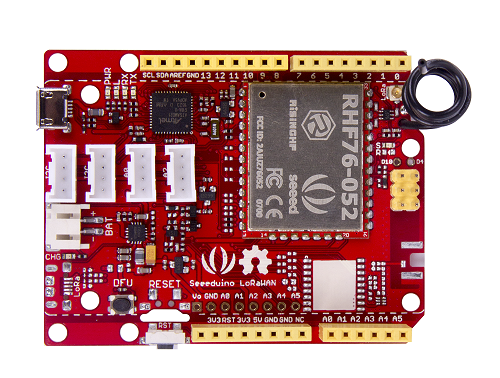
Seeeduino LoRaWAN is an Arduino development board with LoRaWan protocol embedded, through which you can get started quickly to experience LoRa’s advantage in the field of IoT. Based on the communication module RHF76-052AM, Seeeduino LoRaWAN is compatible with LoRaWAN Class A/C and supports a variety of communication frequencies.
The 4 onboard standard Grove connectors allow Seeeduino LoRaWan to connect with hundreds of Grove sensors and actuators from Seeedstudio conveniently, as a result, users are able to be more focus on the application itself without worrying about the compatibility issue between different modules. In addition, the board has embedded an integrated lithium battery management chip that allows the board to be charged by USB interface. In low consumption mode, a full charged lithium battery can power the board for several months.
If you want to build an IoT application quickly, Seeeduino LoRaWAN is your best choice.
| Product Version | Released Date | How to Buy |
|---|---|---|
| Seeeduino LoRaWAN | Dec 20, 2016 |  |
| Seeeduino LoRaWAN W/GPS | Dec 20, 2016 | |
Warning
Please update the firmware when the first time to use it. Please always plug 3.7V Lipo battery in case USB power supply is not sufficient.
Tip
Seeeduino LoRaWAN W/GPS is consist of GPS module.
Features
- Minimum current (3.7V lipo battery) - 2mA
- Minimum current (3.7V lipo battery & remove PWR LED) - 80 uA
Arduino/Processor
- ATSAMD21G18 @ 48MHz with 3.3V logic/power
- Arduino compatible (based on Arduino Zero bootloader)
- Embedded with lithium battery management chip and status indicator led
- 20 GPIOs
- 4 on-board Grove connectors
- 18 x PWM pins
- 6 x analog inputs
- 1 x analog output (A0)
- 3.3V regulator with 200mA output
- Reset button
LoRaWAN/RHF76-052
- 1.45uA sleep current in WOR mode (Spec of the modules, not the board)
- High link budget of 160dB. -140dBm sensitivity and 19dBm Output power.
- Dual band, 434/470MHz and 868/915MHz
- 19dBm@434MHz/470MHz
- 14dBm@868MHz/915MHz
- Support LoRaWAN protocol, Class A/C
- Ultra long range communication
- Ultra low power consumption
- Firmware upgrade
- Small size: 23mm X 28mm with 33 pin SMT package
Warning
Unlike most Arduino & Genuino boards, the Zero runs at 3.3V. The maximum voltage that the I/O pins can tolerate is 3.3V. Applying voltages higher than 3.3V to any I/O pin could damage the board.
Specification
| Item | Value |
|---|---|
| Microcontroller | ATSAMD21G18, 32-Bit ARM Cortex M0+ |
| Operating Voltage | 3.3V |
| Digital I/O Pins | 20 |
| PWM Pins | All but pins 2 and 7 |
| UART | 2 (Native and Programming) |
| Analog Input Pins | 6, 12-bit ADC channels |
| Analog Output Pins | 1, 10-bit DAC |
| External Interrupts | All pins except pin 4 |
| DC Current per I/O Pin | 7 mA |
| Flash Memory | 256 KB |
| SRAM | 32 KB |
| EEPROM | None |
| Clock Speed | 48 MHz |
| Lenght | 68 mm |
| Width | 53 mm |
| Weight | 19.6g(without GPS), 19.9(with GPS) |
Application Ideas
- Internet of Things
- Smart House
- Security
- Smart Grid
- Intelligent Farm
- Intelligent Park
Tip
Use Grove modules to expand your application
There are 4 Grove connects on board. If this is your first time to hear about Grove, please put had on Grove System for more details. In brief, Groves is hundreds of sensor that in standard style, which is consist of sensors, actuators, displays as well as communication.
Hardware Overview
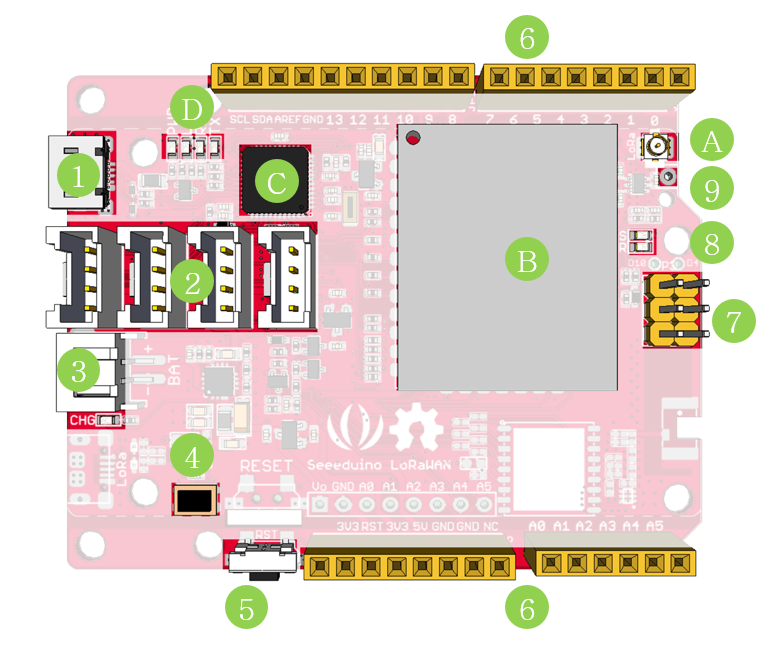
- 1. Micro USB - Programming and supply power to the board
- 2. Grove connectors
- 3. JST2.0 Lipo battery input (3.7V) and charge status led
- 4. DFU Button - Firmware mode button
- 5. Reset Button
- 6. Arduino Pinout
- 7. ICSP pins
- 8. Firmware mode led
- 9. Wire antenna
- A. uFL antenna
- B. RF module - RHF76-052AM
- C. ARM Cortex M0 processor - ATSAMD21G18
- D. LEDs
- RX/TX - blink when data on UART(from/to USB)
- L - an led connect to D13
- PWR - power
Tip
If you want to use the 4 on-board Grove connector, please use digitalWrite(38, HIGH) to open VCC. Otherwise you can’t provide power to Grove modules.
Pin Map
| Pin Name | GPIO Num | External Interrupt | PWM | Analog In | Analog Out | Function |
|---|---|---|---|---|---|---|
| 0 | #0 | YES | YES | RX(Serial) | ||
| 1 | #1 | YES | YES | TX(Serial) | ||
| 2 | #2 | YES | ||||
| 3 | #3 | YES | YES | |||
| 4 | #4 | YES | ||||
| 5 | #5 | YES | YES | |||
| 6 | #6 | YES | YES | |||
| 7 | #7 | YES | ||||
| 8 | #8 | YES | YES | |||
| 9 | #9 | YES | YES | |||
| 10 | #10 | YES | YES | |||
| 11 | #11 | YES | YES | SPI_MOSI | ||
| 12 | #12 | YES | YES | SPI_MISO | ||
| 13 | #13 | YES | YES | SPI_SCK | ||
| SDA | #20 | YES | YES | |||
| SCL | #21 | YES | YES | |||
| A0 | #A0 | YES | YES | YES | YES | |
| A1 | #A1 | YES | YES | YES | ||
| A2 | #A2 | YES | YES | YES | ||
| A3 | #A3 | YES | YES | YES | ||
| A4 | #A4 | YES | YES | YES | Voltage of Battery | |
| A5 | #A5 | YES | YES | YES | Charge Status |
Note
All pins can act as Digital Input and Output
Getting Started - Arduino IDE
Note
This chapter is based on Win10 and Arduino IDE v1.6.0
First you need to install the latest Arduino IDE, and ADD Seeeduino LoRa to your Arduino IDE.
Install the Driver (For Windows)
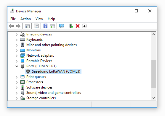
When the first time to insert the board, you should get a USB COM device name Seeeduino LoRaWAN that need to install a driver. Click on the below button to download driver for the board.

To make sure the driver was installed successful, open your Device Manager to see if Seeeduino LoRaWAN exists.
Blink
Now we can upload our first demo - Blink to Seeeduino LoRaWAN.
Open your Arduino IDE and click on File > Examples > 01.Basics > Blink to open the sketch or copy the blow code:
// the setup function runs once when you press reset or power the board
void setup() {
  // initialize digital pin 13 as an output.
  pinMode(13, OUTPUT);
}

// the loop function runs over and over again forever
void loop() {
  digitalWrite(13, HIGH);   // turn the LED on (HIGH is the voltage level)
  delay(1000);              // wait for a second
  digitalWrite(13, LOW);    // turn the LED off by making the voltage LOW
  delay(1000);              // wait for a second
}
And Then,
- Click on Tools > Board > Seeeduino LoRaWAN
- Click on Tools > Port to select a right port number. (Don’t choose COM1)
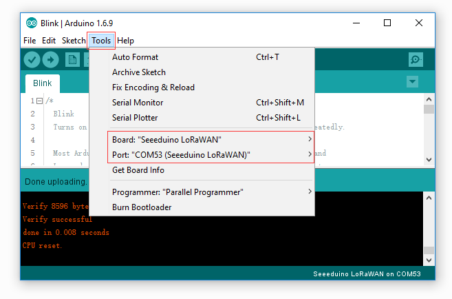
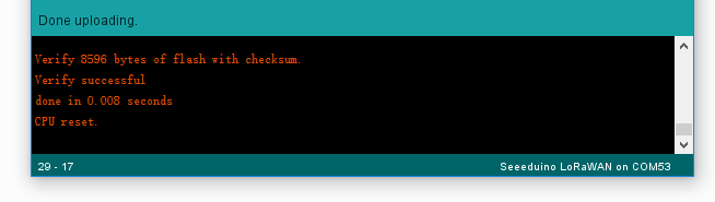
Then click on the Upload button on the left-top of Arduino IDE, seconds later the sketch was uploaded successful.
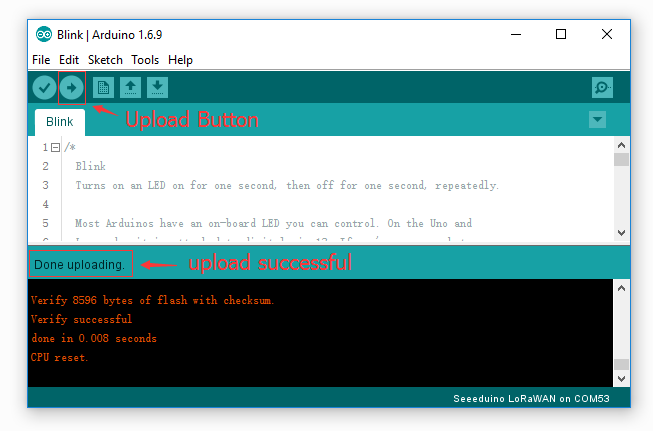
If the uploading is success, you should the some info in red and please the on-board LED, it’s blinking.
Battery
You can power the board via a 3.7V Lipo battery. There’s a JST2.0 cable included, use it if you can’t get a battery with JST2.0 connector.
Warning
Make sure the positive and negative end of your battery is connected right, otherwise the board may be damaged.
Charge status pin and positive pin of the battery had beed connect to A4 and A5, which allow you to detect the charge status and measure voltage of the battery via coding.
Copy and upload the below code to detect the battery status.
// battey of Seeeduino LoRaWAN

const int pin_battery_status  = A5;
const int pin_battery_voltage = A4;

void setup() {
    SerialUSB.begin(115200);
    pinMode(pin_battery_status, INPUT);
}

void loop() {

    int a = analogRead(pin_battery_voltage);
    float v = a/1023.0*3.3*11.0;        // there's an 1M and 100k resistor divider
    SerialUSB.print(v, 2);
    SerialUSB.print('\t');
    SerialUSB.println(digitalRead(pin_battery_status));

    delay(1000);
}
Note
Charge status return 0 while charging, return 1 while charge done or no battery insert.
Send and Receive Example
There is a well written library for the LoRaWAN modules, for simple applications you even don’t need to know much about the protocol about LoRa, which is complex and hard to read. And please note that you till need some acknowledge about LoRa protocol if you want an advanced application. You don’t need to download the library, it’s included in the package already. You can open it at File > Examples > LoRaWAN.
You need 2 piece of Seeeduino LoRaWAN to complete this example, one for sending and another for receiving.
Sending
Open your Arduino IDE and click on File > Examples > LoRaWAN > p2p_tx to open the sketch or you can copy the code below. This sketch will broadcast a string “Hello World!” every 3000 ms.
// Seduino LoRaWAN - TX example
#include <LoRaWan.h>

void setup(void)
{
    SerialUSB.begin(115200);
    lora.init();
    lora.initP2PMode(433, SF12, BW125, 8, 8, 20);
}

void loop(void)
{
    lora.transferPacketP2PMode("Hello World!");
    SerialUSB.println("Send string.");
    delay(3000);
}
Receiving
Open your Arduino IDe and click on File > Examples > LoRaWAN > p2p_rx to open the sketch or you can copy the code below.
// Seduino LoRaWAN - RX example
#include <LoRaWan.h>

unsigned char buffer[128] = {0, };

void setup(void)
{
    SerialUSB.begin(115200);
    lora.init();
    lora.initP2PMode(433, SF12, BW125, 8, 8, 20);
}

void loop(void)
{
    short length = 0;
    short rssi = 0;

    memset(buffer, 0, 128);
    length = lora.receivePacketP2PMode(buffer, 128,  &rssi, 1);

    if(length)
    {
        SerialUSB.print("Length is: ");
        SerialUSB.println(length);
        SerialUSB.print("RSSI is: ");
        SerialUSB.println(rssi);
        SerialUSB.print("Data is: ");
        for(unsigned char i = 0; i < length; i ++)
        {
            SerialUSB.print("0x");
            SerialUSB.print(buffer[i], HEX);
            SerialUSB.print(" ");
        }
        SerialUSB.println();
    }
}
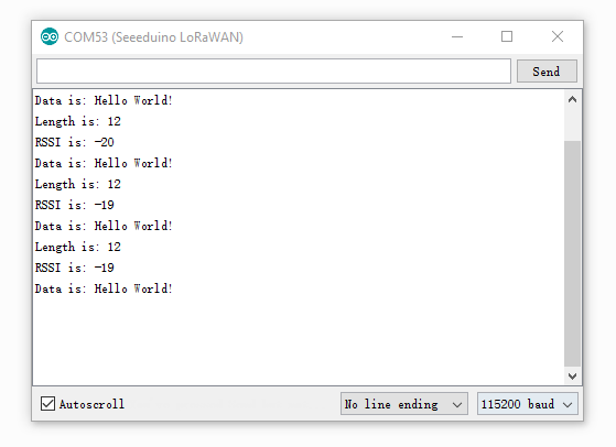
After both of the sketch is well uploaded, open the serial monitor of the receiving board, check if you can get some data as below.
Note
There will be a gateway kit for LoRa soon, and we will add getting started about APB and OTAA mode at wiki of the kit.
Examples
We had provide many useful examples. You can open File > Examples > LoRaWan get more details. Those examples include:
- ABP
- OTAA
- p2p-rx
- p2p-tx
GPS Data
Note
This chapter works with Seeeduino LoRaWAN W/GPS only.
Copy below code you Seeeduino LoRaWAN W/GPS.
void setup()
{
    Serial.begin(9600);
    SerialUSB.begin(115200);
}

void loop()
{
    while(Serial.available())
    {
        SerialUSB.write(Serial.read());
    }
    while(SerialUSB.available())
    {
        Serial.write(SerialUSB.read());
    }
}
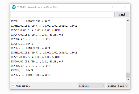
Open Serial Monitor then you will get data from GPS.
Low Power
The minimum current is 80uA(for Seeeduino LoRaWAN) under our testing. Please follow below steps.
- Remove PWR LED (If you don’t remove this LED, the current will > 2mA)
- Remove CHG LED
- Upload below code to your board.
#include <LoRaWan.h>
#include <EnergySaving.h>

EnergySaving nrgSave;

void blink()
{
    for(unsigned char i = 0; i < 5; i ++)
    {
        digitalWrite(13,HIGH);
        delay(500);
        digitalWrite(13,LOW);
        delay(500);
    }
}

void setup()
{
    for(unsigned char i = 0; i < 26; i ++)      // important, set all pins to HIGH to save power
    {
        pinMode(i, OUTPUT);
        digitalWrite(i, HIGH);
    }

    lora.init();
    blink();
    lora.setDeviceLowPower();
    blink();
    nrgSave.begin(WAKE_EXT_INTERRUPT, 7, dummy);    // buton on D7 to wake up the board
    nrgSave.standby();
}

void loop()
{
    blink();
    nrgSave.standby();
}

void dummy(void)
{
    // do something
}

// END File
Update firmware
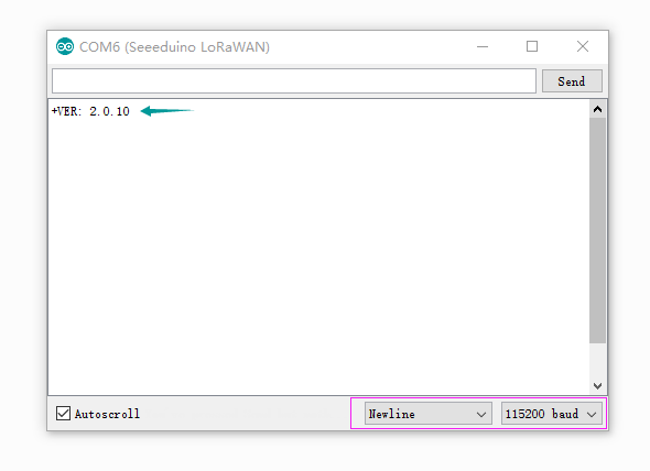
The firmware version of is 2.0.10, if you want to update firmware, few steps need to follow.
If you want to check version of you board, please upload below code to your board.
void setup()
{
    Serial1.begin(9600);
    SerialUSB.begin(115200);
}

void loop()
{
    while(Serial1.available())
    {
        SerialUSB.write(Serial1.read());
    }
    while(SerialUSB.available())
    {
        Serial1.write(SerialUSB.read());
    }
}
Open your Serial Monitor and INPUT
AT+VER
Then you will get the version of your board.
Step1
Copy and upload below code to your board.
// Update firmware to RHF76-052AM
#include <Arduino.h>

void setup()
{
    SerialDBG.begin(115200);
    SerialUSB.begin(115200);
}

void loop()
{
    while(SerialDBG.available())
    {
        SerialUSB.write(SerialDBG.read());
    }
    while(SerialUSB.available())
    {
        SerialDBG.write(SerialUSB.read());
    }
}
Step2
Remove the board form USB and reconnect again, then press the DFU Button, after the Firmware mode led blinking you can go to the next step.
Step3
Click to download the latest firmware, which is a .bin file.

Step4
Open PuTTy and connect to the board
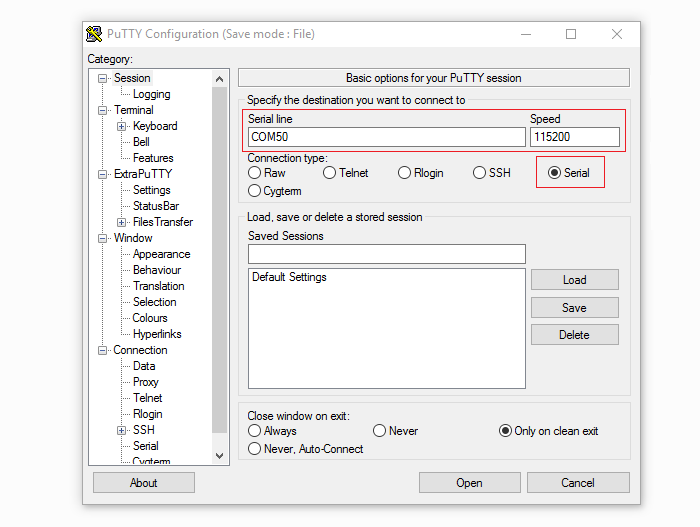
Tip
You can find the latest PuTTy here: http://www.extraputty.com/download.php
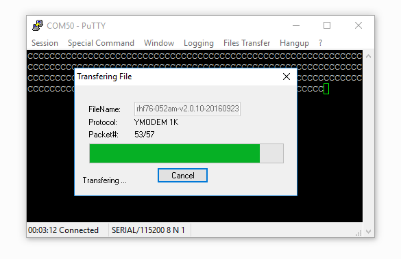
Step5
After connect your board to PuTTy successful, you will find the char ‘C’ print on the monitor continually. Click on Files Transfer > Ymodem > Send, and select the .bin file we had downloaded at Step4.
Then the updating is started.
Resources
- Schematics in Eagle
- Sketchup file(3D)
- CE certification of RHF 76-052
- RHF76-052 Firmware V2.0.10
- RHF76-052 Firmware V2.1.16
- Datasheet of RHF76-052AM
- Datasheet of GPS Chip L70B-M39
Help us make it better
Welcome to the new documentation system of Seeed Studio. We have made a lot of progress comparing to the old wiki system and will continue to improve it to make it more user friendly and helpful. The improvement can't be done without your kindly feedback. If you have any suggestions or findings, you are most welcome to submit the amended version as our contributor via Github or give us suggestions in the survey below, it would be more appreciated if you could leave your email so that we can reply to you. Happy Hacking!