Replacement LCD Screen for DSO nano
Introduction

Replacement LCD for DSO nano, purchase this if you broke the original one on your DSO. Please note that you need basic soldering skill to install this LCD to your DSO.
Usage
Hardware Installation
Dismantle your DSO nano
Dismantel your DSO nano is pretty easy, but it’s still worth writing a tutorial to let people know what does DSO nano look inside before open it.
Note: This tutorial is for information purposes, Dismantle the DSO nano and follow this tutorial at your own risk!
You will need:
-
A sharp knife (Or something else sharply)
-
A 1.4mm screwdriver
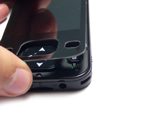
First you need to remove the top panel by using a sharp knife. The top panel is attached with the body by glue, be sure to do this slowly, or you will damage the acrylic panel .

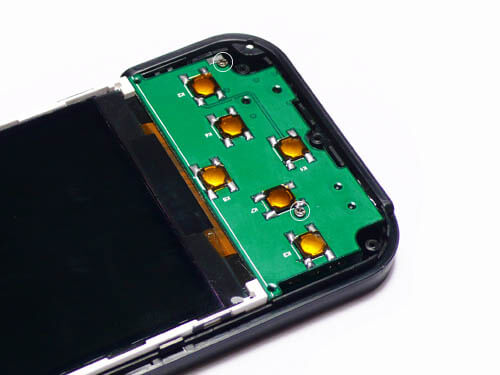
Here you can see 6 screws(marked with white circle) after the top panel is removed. Remove them with a 1.4mm screwdriver, then go to the next step.
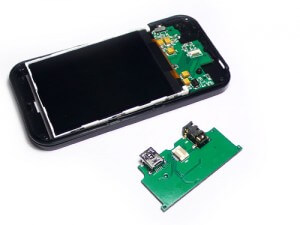
Remove the rest 2 screws, now you should be able to take the sub-board apart from the motherboard.
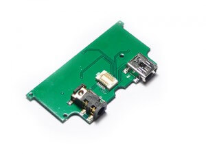
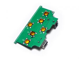
Sub-Board detailed pictures. 6 metal dome buttons were soldered on the top side, and 1×3.5MM TSR connector, 1X Mini usb connector on bottom. There’s also a board to board connector to attach the 2 separated PCB.
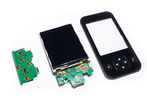
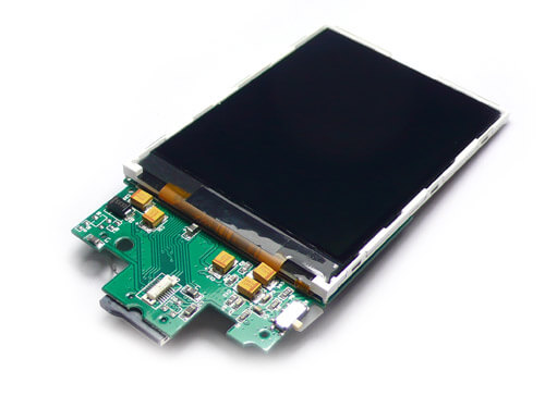
Here we go, now you can take the screen and motherboard away from the case.
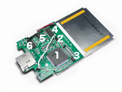
-
controller: STM32
-
stabilized voltage supply : 3.3V voltage output
-
stabilized voltage supply : 3.0V voltage output
-
stabilized voltage supply : use a P3232 RS-232 transceivers to output +5V and -5V voltage
-
general purpose dual J-FET operation amplifier : to separate and scale the input signal
-
8-Channel Analog Multiplexer : change the match channel for different V/div
Help us make it better
Welcome to the new documentation system of Seeed Studio. We have made a lot of progress comparing to the old wiki system and will continue to improve it to make it more user friendly and helpful. The improvement can't be done without your kindly feedback. If you have any suggestions or findings, you are most welcome to submit the amended version as our contributor via Github or give us suggestions in the survey below, it would be more appreciated if you could leave your email so that we can reply to you. Happy Hacking!