Raspberry Pi Relay Board v1.0
Introduction
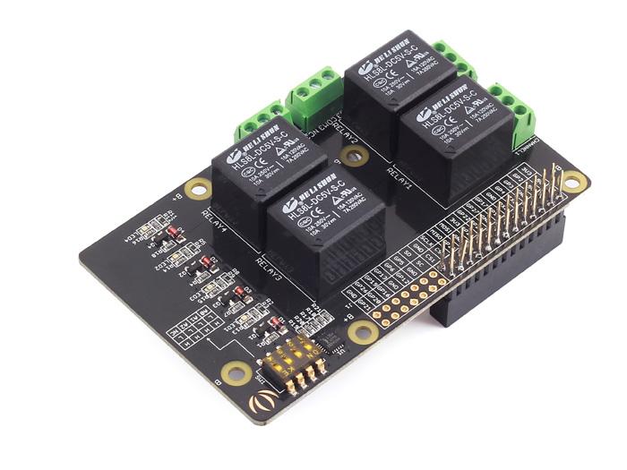
The Relay Shield utilizes four high quality relays and provides NO/NC interfaces that control the load of high current. Which means it could be a nice solution for controlling devices that couldn’t be directly controlled by IIC bus. Standardized shield form factor enables smoothly connection with the Raspberry Pi. The shield also has four dynamic indicators show the on/off state of each relay.

Features
- Raspberry Pi compatible
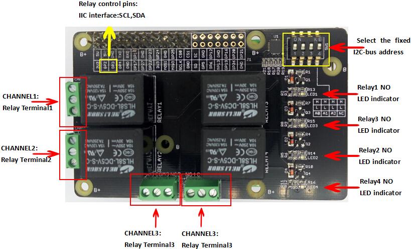
- Interface: IIC, Three hardware SW1 (1, 2, 3) select the fixed I2C-bus address
- Relay screw terminals
- Standardized shield shape and design
- LED working status indicators for each relay
- COM, NO (Normally Open), and NC (Normally Closed) relay pins for each relay
- High quality relays
- Working status indicators for each relay
Specifications
| Item | Min | Typical | Max | Unit |
|---|---|---|---|---|
| Supply Voltage | 4.75 | 5 | 5.5 | VDC |
| Working Current | 10 | / | 360 | mA |
| Switching Voltage | / | / | 30/250 | VDC/VAC |
| Switching Current | / | / | 15 | A |
| Frequency | / | 1 | / | HZ |
| Switching Power | / | / | 2770VA/240 | W |
| Relay Life | 100,000 | / | / | Cycle |
| Dimensions | 91.20 * 56.15 * 32 | mm | ||
Caution
Place 2 layers of electrical tape on the top of the Arduino's usb connector. This will prevent the relay shield from making contact. Do not operate voltage more than 35V DC.Hardware Overview
Usage
This section was written by John M. Wargo, here we would like to express our gratitude to John’s contribution. We have amended the original text a little to fit it in the whole Seeed’s document. Please click here to visit the original document on his website.
The steps for installing the board and verifying that it works includes the following steps:
- Step1. Mount the Relay board on the Raspberry Pi
- Step2. Enable the Raspbian I2C software interface
- Step3. Validate that the Raspberry Pi recognizes the board
- Step4. Run some Python code to exercise the board
Step1. Mounting the Relay Board
Mounting the board is easy, it comes with the appropriate female headers you need to mount it on any Raspberry Pi board with male headers. Note: You’ll have to add male headers to the Raspberry Pi Zero to use the board.
We recommend you putting some electrical tape on top of the Raspberry Pi Ethernet port before mounting the board. If you mount the board without using standoffs (as I’ve done in the example figure below), there’s a chance the board will make contact with the Ethernet port housing and cause a problem.
 Figure 1
For a production project, We’d definitely recommend using standoffs to hold the two boards in place.
The relay board is configured for an older Raspberry Pi with a 26 pin header, so when you connected it to a Raspberry Pi with 40 pin headers, you’ll need to shift it all the way to the side like We’ve shown in the figure. If you don’t align the pins correctly, you’ll have problems later as it simply won’t work.
Enabling I2C
The relay board communicates with the Raspberry Pi through an I2C interface https://en.wikipedia.org/wiki/I%C2%B2C. This interface is disabled by default in the Pi’s Raspbian OS, so you’ll have to turn it on before you can use the board. Power up the Pi and let it boot to the graphical interface. When it’s up and running, open the Pi menu, select Preferences, then Raspberry Pi Configuration as shown in the following figure:
 Figure 2
In the window that opens, select the Interfaces tab as shown in the following figure. Enable the option next to I2C as shown in the figure and click the OK button to continue. When you reboot the PC, the Pi should see the relay board. In the next section, we’ll verify that the Pi sees the relay board.
 Figure 3
Validating the Raspberry Pi Sees the Relay Board
With the I2C interface enabled, it’s time to make sure the Raspberry Pi sees the relay board. Open a terminal window on the Pi and execute the following command:
i2cdetect -y -r 1
The application will display a dump of the recognized I2C devices as shown in the following figure. In this example, there’s only one I2C board on the system, the relay board configured at an address of 20. You’ll see how this value is important later in this article.
 Figure 4
You’re supposed to be able to use switches on the relay board to set the I2C address, there are 4 DIP switches on the board, let’s see what happens when you change them.
There are four switches, three labeled A0 through A2, and one labeled NC. The NC means No Connection. Each switch has a high and a low setting, so the following table will lay out how to use them to set an I2C address for the board:
| A0 | A1 | A2 | Address |
|---|---|---|---|
| High | High | High | 20 |
| Low | High | High | 21 |
| High | Low | High | 22 |
| High | High | Low | 24 |
| High | Low | Low | 26 |
| Low | Low | Low | 27 |
Running the Test Application
Please use the test code from github repository. Grab the code from there and you’ll be able to easily complete the following step.
To run the test application, open a terminal window, navigate to where you’ve extracted the sample application and run the application using the following command:
python ./seeed_relay_test.py
 Figure 4
When prompted for input, you’ll type commands to turn the relays on and off:
- Typing 1on, 2on, 3on, or 4on and pressing enter will cause the specified relay to turn on.
- Typing 1off, 2off, 3off, or 4off and pressing enter will cause the specified relay to turn off
- Typing allon or alloff will turn all relays on or off.
Using The Python Module
To use the module in your own Python applications, copy the module (relay_lib_seeed.py) into your project folder, then import the module in your Python application by adding the following line to the beginning of your application:
from relay_lib_seeed import *
This exposes a series of functions to your application:
- relay_on(int_value) - Turns a single relay on. Pass an integer value between 1 and 4 (inclusive) to the function to specify the relay you wish to turn on. For example: relay_on(1) will turn the first relay (which is actually relay 0 internally) on.
- relay_off(int_value) - Turns a single relay on. Pass an integer value between 1 and 4 (inclusive) to the function to specify the relay you wish to turn on. For example: relay_on(4) will turn the first relay (which is actually relay 3 internally) off.
- relay_all_on() - Turns all of the relays on simultaneously.
- relay_all_off() - Turns all of the relays off simultaneously.
The module exposes a configuration value you will want to keep in mind as you work with the board:
# 7 bit address (will be left shifted to add the read write bit)
DEVICE_ADDRESS = 0x20
Remember that value? 20? The board defaults to this address. If you change the switches on the board, you will need to update this variable accordingly.
To see the module in action, open a terminal window on the Raspberry Pi, navigate to the folder where you extracted this repository’s files, and execute the following command:
python ./relay_lib_seeed_test.py
The application will:
- Turn all of the relays on for a second
- Turn all of the relays off
- Cycle through each of the relays (1 through 4) turning each on for a second
The module will write indicators to the console as it performs each step as shown in the following figure:
 Figure 6
LEDs on the relay board (one for each relay) will illuminate when the relays come one. On my board, they weren’t in sequence, so don’t expect them to light in order.
The code that does all this looks like the following:
# turn all of the relays on
relay_all_on()
# wait a second
time.sleep(1)
# turn all of the relays off
relay_all_off()
# wait a second
time.sleep(1)
# now cycle each relay every second in an infinite loop
while True:
for i in range(1, 5):
   relay_on(i)
   time.sleep(1)
   relay_off(i)
That’s it, that’s all there is to it. Enjoy.
Resources
- Raspberry_Pi_Relay_Board_v1.0_sch_pcb
- Raspberry_Pi_Relay_Board_v1.0_PDF
- HLS8L Datasheet
- PCAL9535A Datasheet
- Test Code
Help us make it better
Welcome to the new documentation system of Seeed Studio. We have made a lot of progress comparing to the old wiki system and will continue to improve it to make it more user friendly and helpful. The improvement can't be done without your kindly feedback. If you have any suggestions or findings, you are most welcome to submit the amended version as our contributor via Github or give us suggestions in the survey below, it would be more appreciated if you could leave your email so that we can reply to you. Happy Hacking!