Protoshield Kit for Arduino
Introduction

Build your own Arduino shield using the compact and flexible Proto Shield kit. Solder together a limitless range of circuits and reuse it in all your Arduino projects. A standard 0.1” prototyping grid accepts commonly used through-hole parts and chips. Basic components (resistors, potentiometer, LEDs, switches) are included to help you get started with your custom shield.

Features
-
Arduino compatible
-
Large 0.1 inch pitch prototyping area
-
A variety of through-hole sizes to fit most parts
-
Arduino UART and I2C port pin breakouts for easy external communication interfacing
-
Dual ISP breakouts for easy programming and stacking
-
3.3 volt, 5 volt, and ground power rails are easily available anywhere on the board
-
Breadboard style prototyping area
-
USB type B connector
-
Basic components included (buttons, switches, LEDs, resistors, USB jack)
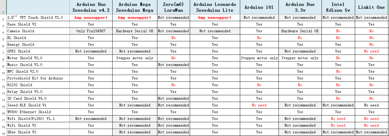
Compatibility
We have produced a lot of extension board that can make your platform board more powerful, however not every extension board is compatible with all the platform board, here we use a table to illustrate how are those boards compatible with platform board.
Note
Please note that “Not recommended” means that it might have chance to work with the platform board however requires extra work such as jump wires or rewriting the code. If you are interested in digging more, welcome to contact with techsupport@seeed.cc.
Click to see full picture
Components included in the kit
-
1 Arduino compatible Proto Board
-
1 B type USB connector
-
1 40-pin 2.54mm male long header
-
1 40-pin 2.54mm female header
-
2 40-pin 2.54mm male headers
-
1 40-pin 2.54mm spacer
-
3 8-pin 2.54mm female headers
-
1 6-pin 2.54mm female header
-
1 ISP female pin header
-
1 ISP male pin header
-
1 10k ohm potentiometer
-
4 1k ohm resistors
-
2 10k ohm resistors
-
2 3mm red LEDs
-
2 3mm green LEDs
-
1 3mm dual color LED
-
4 Mini push button switches
-
2 DPDT switches
Board trace schematic

Assembly
Step 1: Solder the Red LED to the holes in the Power Socket outline. Be sure to match the flat side of the LED with the outline on the board. Solder the green LED to the holes in the pin13 outline on the board, again, matching the flat side of the LED to the board outline. Solder two 1K resistors to R1 and R2. Solder Reset button and ISP header per the picture below. Note: The reset button is easier to install if you insert it before inserting the ISP header.

Step 2: Solder the female and male connectors. Note: solder ADC6 and ADC7 ONLY if your are using a Seeeduino. When using an Arduino, do NOT solder ADC6 and ADC7.


Step 3: Solder the USB connector to the USB port, and the potentiometer in the 80 mil holes. Solder the bottom left Power pins to suit your project.

Your finished kit should look similar to the picture above.
Resources
Help us make it better
Welcome to the new documentation system of Seeed Studio. We have made a lot of progress comparing to the old wiki system and will continue to improve it to make it more user friendly and helpful. The improvement can't be done without your kindly feedback. If you have any suggestions or findings, you are most welcome to submit the amended version as our contributor via Github or give us suggestions in the survey below, it would be more appreciated if you could leave your email so that we can reply to you. Happy Hacking!