Grove - UART Wi-Fi
Introduction

Grove - UART WiFi is a serial transceiver module featuring the ubiquitous ESP8266 IoT SoC. With integrated TCP/IP protocol stack, this module lets your micro-controller interact with WiFi networks with only a few lines of code. Each ESP8266 module comes pre-programmed with an AT command set firmware, meaning you can send simple text commands to control the device. The SoC features integrated WEP, WPA/WPA2, TKIP, AES, and WAPI engines, can act as an access point with DHCP, can join existing WiFi networks and has configurable MAC and IP addresses.

Features
- Grove 4-pin connector (RX,TX,VCC,GND)
- 802.11 b/g/n protocol (2.4GHz)
- WiFi Direct (P2P), soft-AP
- Supports three modes: AP, STA and AP+STA coexistence mode
- Integrated TCP/IP protocol stack
- LwIP (lightweight IP)
- Integrated low power 32-bit CPU could be reprogrammed as an application processor
- Integrated temperature sensor
- Serial UART Interface
- Multi-queue QoS management
- Wake up and transmit packets in < 2ms
- Metal shielding
- On-board ceramic antenna
- Reset switch
Tip
More details about Grove modules please refer to Grove System
Hardware Overview
Here is block diagram of Grove - UART WiF module which consists of following parts.
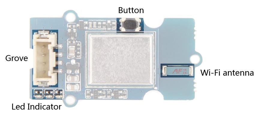
- Grove - Used to connect to a processor through socket on a base board such as a Seeeduino or Grove Base Shield.
- WiFi antenna - Antenna for ESP8266(Module model)
- Button - With multi-functions
- Reset - Press down and release quickly.
- Set ESP8266(Module model) into UART boot mode - Press and hold button until centred red LED indicator light on.
- Led Indicator - Used to indicate working status and for operations by user.
- Left - a blue LED indicator - Controlled by user through command “AT+LEDON” and “AT+LEDOFF”.
- Middle - a red LED indicator - light on while Wifi connected or go into UART boot mode
- Right - a green LED indicator - light on while power on.
Specifications
- Input voltage: 3V / 5V
- Baud Rate: 115200
- Based on ESP8266 ESP-06 SoC
- AT Firmware: esp_iot_sdk_v1.1.0 + Seeed modifications:
- 2x additional AT commands to control blue Link LED.
- Register red WiFi LED to the ESP8266 wifi state LED.
- AT command set
- SDIO 1.1/2.0, SPI, UART
- Five power states: OFF, DEEP_SLEEP, SLEEP, WAKEUP and ON.
- Standby power consumption of < 1.0mW (DTIM=3)
- Integrated TR switch, balun, LNA, power amplifier and matching network
- Integrated PLLs, regulators, DCXO and power management units
- +19.5dBm output power in 802.11b mode
- Power down leakage current of <10uA
- Hardware accelerators for CCMP (CBC-MAC, counter mode), TKIP (MIC, RC4), WAPI (SMS4), WEP (RC4), CRC
- WPA/WPA2 PSK, and WPS driver
- A-MPDU & A-MSDU aggregation & 0.4ms guard interval
- Dimensions: 25.43mm x 20.35mm
Ultra-low power technology
The ESP8266 was designed to achieve very low energy consumption with patented power management technology that reduces non-essential functions and regulates sleep patterns. There are five power states:
- OFF
- DEEP_SLEEP - the real-time clock runs but all other parts of the chip are closed
- SLEEP - consumes less than 12uA with only real-time clock and watchdog running. The chip will wake on MAC, host, RTC or external interrupt.
- WAKEUP - the system is changing from a sleep to on state. Crystal oscillator and PLL are enabled.
- ON - consumes less than 1.0mW (DTIM = 3) or 0.5mW (DTIM = 10).
The Real-time clock can be programmed to wake the ESP8266 within a specified period of time.
The higher the DTIM period, the longer the device may sleep and therefore the more power the device may potentially save.
To meet the power requirements of mobile applications and wearable electronics, to reduce the overall power consumption, the PA output power can be customised in the firmware.
Application Ideas
- Home automation
- Sensor networks
- Mesh networking
- Wearable electronics
- Baby monitor
- Network camera
- Industrial wireless control
- WiFi beacons
- Smart power plug
- Location-aware applications
Getting Started
After this section, you can make Grove - UART WiFi run with only few steps.
Preparations
Now we are making a demo for wireless access point(AP) scan which require following modules.
If this is your first time using Seeeduino Lite, please refer to Seeeduino Lite’s wiki
Seeeduino Lite is compatible with Arduino which works as simple as Arduino.
If this is your first time using Arduino, Please put hand on here to start your Arduino journey.
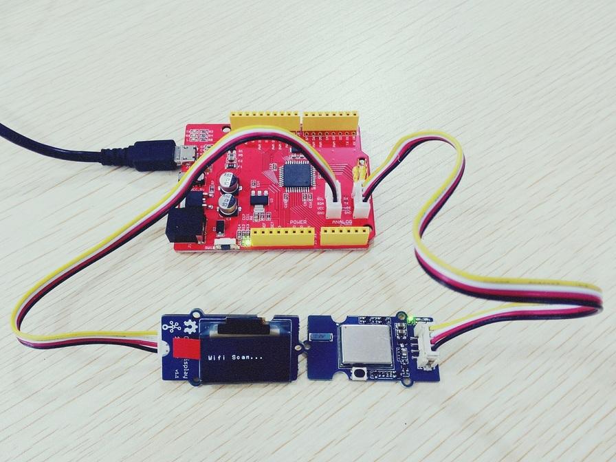
Connecting hardware
Seeeduino Lite got Grove socket for connecting two module mentioned above: Grove - OLED Display 1.12 and Grove - Uart Wi-Fi.
They are:
- Grove - OLED Display 1.12 - connection to I2C socket
- Grove - UART Wifi - connection to Serial socket * As shown below:
Download
Click here to download testing code and decompress it to any folders(e.g. Drive D or desktop)
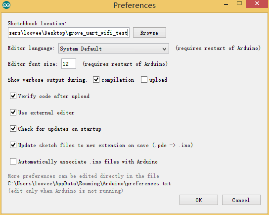
Now you need simple configurations for Arduino sketchbook.
Launch Arduino IDE and click File>Preferences and add absolute location for downloaded testing code at Sketchbook location .
After configurations, please restart Arduino, click File>Sketchbook and choose grove_uart_wifi_wiki after which testing code will show up.
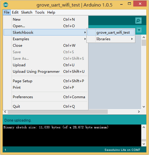
Click Tools>Board to choose Seeeduino Lite and select respective serial port.
Now click Upload(CTRL+U) to burn testing code. Please refer to here for any error prompt and you can also add comment on forum
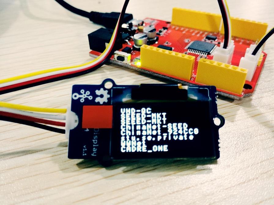
Review Results
After upload completed, you can see AP identifier on OLED display.Following AP identifiers are found in our office.
Firmware update
Our module board got a firmware burned into it for factory settings, you can burn other firmware to it if you like. Click here to download source code of factory setting firmware.
Preparations
- A USB to serial converter is required for firmware updating, you can choose UartSBee V5 we offered if you don’t know where to get one.
- A Grove-Jump converting cable is required and we also offered for sale. Click here to check.
- A micro USB cable(type A to type C) is required.
Connecting hardware
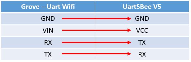
1.Connect one end of Grove-Jump converting cable with grove socket on Grove - Uart Wifi and connect other end with UartSBee V5 which shown as following.
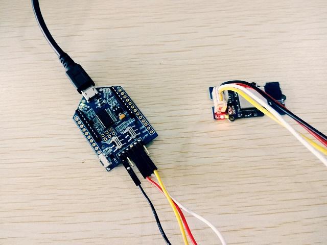
2.Then connecting cables like following figure:
Download burning tools
Operation steps
Now make sure you have downloaded burning software and bin file of firmware. Let us start burning to board.
- Press and hold button until red LED indicator light on which indicate it is ready to burn firmware.
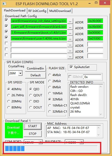
- Start executable files in FLASH DOWNLOAD TOOLS files (double click) to make configurations like following steps:
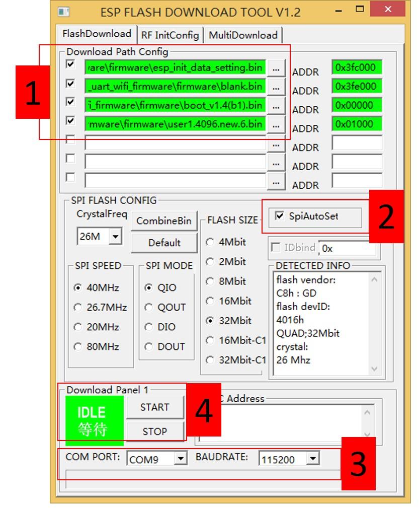
1. Choose desired files from firmware bin file downloaded.
2. Check SpiAutoSet.
3. Choose respective COM port and BAUDRATE.
Click to START to burn firmware
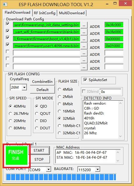
- Progress bar will be displayed in firmware-burning process.
- Finally, firmware-burning is done.
AT Commands
Using Espressif Systems ESP8266 AT Instruction Set Version 0.24 with SeeedStudio additions.
Basic AT Commands
| Command | Description |
|---|---|
| AT | Test AT startup |
| AT+RST | Restart module |
| AT+GMR | View version info |
| AT+GSLP | Enter deep-sleep mode |
| ATE | Enable/Disable AT commands echo |
| AT+RESTORE | Factory Reset |
| AT+UART | UART configuration(Deprecated) |
| AT+UART_CUR | UART current configuration (Won’t save to Flash) |
| AT+UART_DEF | UART default configuration (Save to Flash) |
| AT+SLEEP | Sleep mode |
| AT+RFPOWER | Set RF TX Power |
| AT+RFVDD | Set RF TX Power according to VDD33 |
WiFi AT Commands
| Command | Description |
|---|---|
| AT+CWMODE | WIFI mode (Deprecated) |
| AT+CWMODE_CUR | Current WIFI mode (Won’t save to Flash) |
| AT+CWMODE_DEF | Default WIFI mode (Save to Flash) |
| AT+CWJAP | Connect to AP (Deprecated) |
| AT+CWJAP_CUR | Current Connect to AP (Won’t save to Flash) |
| AT+CWJAP_DEF | Default Connect to AP (Save to Flash) |
| AT+CWLAP | Lists available APs |
| AT+CWQAP | Disconnect from AP |
| AT+CWSAP | Configure softAP (Deprecated) |
| AT+CWSAP_CUR | Configure current softAP (Won’t save to Flash) |
| AT+CWSAP_DEF | Configure default softAP (Save to Flash) |
| AT+CWLIF | List stations connected to softAP |
| AT+CWDHCP | Enable/Disable DHCP (Deprecated) |
| AT+CWDHCP_CUR | Current Enable/Disable DHCP (Won’t save to Flash) |
| AT+CWDHCP_DEF | Default Enable/Disable DHCP (Save to Flash) |
| AT+CWAUTOCONN | Connect to AP automatically when power on |
| AT+CIPSTAMAC | Set station mac address (Deprecated) |
| AT+CIPSTAMAC_CUR | Set station mac address (Won’t save to Flash) |
| AT+CIPSTAMAC_DEF | Set station mac address (Save to Flash) |
| AT+CIPAPMAC | Set softAP mac address (Deprecated) |
| AT+CIPAPMAC_CUR | Set softAP mac address (Won’t save to Flash) |
| AT+CIPAPMAC_DEF | Set softAP mac address (Save to Flash) |
| AT+CIPSTA | Set station IP address (Deprecated) |
| AT+CIPSTA_CUR | Set station IP address (Won’t save to Flash) |
| AT+CIPSTA_DEF | Set station IP address (Save to Flash) |
| AT+CIPAP | Set softAP IP address (Deprecated) |
| AT+CIPAP_CUR | Set softAP IP address (Won’t save to Flash) |
| AT+CIPAP_DEF | Set softAP IP address (Save to Flash) |
| AT+CWSTARTSMART | Start SmartConfig |
| AT+CWSTOPSMART | Stop SmartConfig |
TCP/IP AT Commands
| Command | Description |
|---|---|
| AT+CIPSTATUS | Get connection status |
| AT+CIPSTART | Establish TCP connection or register UDP port |
| AT+CIPSEND | Send data |
| AT+CIPSENDEX | Send data, if |
| AT+CIPSENDBUF | Write data into TCP-send-buffer |
| AT+CIPBUFRESET | Reset segment ID count |
| AT+CIPBUFSTATUS | Check status of TCP-send-buffer |
| AT+CIPCHECKSEQ | Check if a specific segment is sent or not |
| AT+CIPCLOSE | Close TCP/UDP connection |
| AT+CIFSR | Get local IP address |
| AT+CIPMUX | Set multiple connections mode |
| AT+CIPSERVER | Configure as server |
| AT+CIPMODE | Set transmission mode |
| AT+SAVETRANSLINK | Save transparent transmission link to Flash |
| AT+CIPSTO | Set timeout when ESP8266 runs as TCP server |
| AT+CIUPDATE | Upgrade firmware through network |
| AT+PING | Ping an IP address or hostname |
Seeed AT Commands
| Command | Description |
|---|---|
| AT+LEDON | Turn the blue LINK led on |
| AT+LEDOFF | Turn the blue LINK led off |
Resources
- Schematic in PDF
- Schematic in Eagle
- Espressif Systems ESP8266
- Espressif Systems ESP8266 AT Instruction Set - v0.24
- http://www.esp8266.com
- ESP-06
- ESP8266 on Hackaday
- https://nurdspace.nl/ESP8266
Help us make it better
Welcome to the new documentation system of Seeed Studio. We have made a lot of progress comparing to the old wiki system and will continue to improve it to make it more user friendly and helpful. The improvement can't be done without your kindly feedback. If you have any suggestions or findings, you are most welcome to submit the amended version as our contributor via Github or give us suggestions in the survey below, it would be more appreciated if you could leave your email so that we can reply to you. Happy Hacking!