Grove - Tilt Switch
Introduction
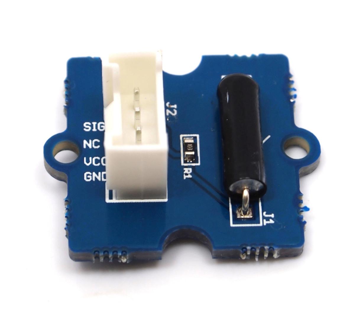
The Grove-Tilt Switch is the equivalent of a button, and is used as a digital input. Inside the tilt switch is a pair of balls that make contact with the pins when the case is upright. Tilt the case over and the balls don’t touch, thus not making a connection. It is wired to the SIG line, NC is not used on this Grove.

Features
- Grove Interface
- Easy to use
- Simple Grove module
Tip
More details about Grove modules please refer to Grove System
Specifications
| Item | Min | Typical | Max | Unit |
|---|---|---|---|---|
| Voltage | 4.75 | 5.0 | 5.25 | V |
| Connecting Angle | 10° ~170° | - | ||
| Disconnect angle | 190° ~350° | - | ||
| Electrical Life | 100,000 | Cycle | ||
Platforms Supported
Usage
With Arduino
The SIG pin of the Grove - Tilt Switch output LOW normally. When the Tilt Switch is upright, a pair of balls inside the tilt switch will contact with the pins and the SIG pin will output HIGH.
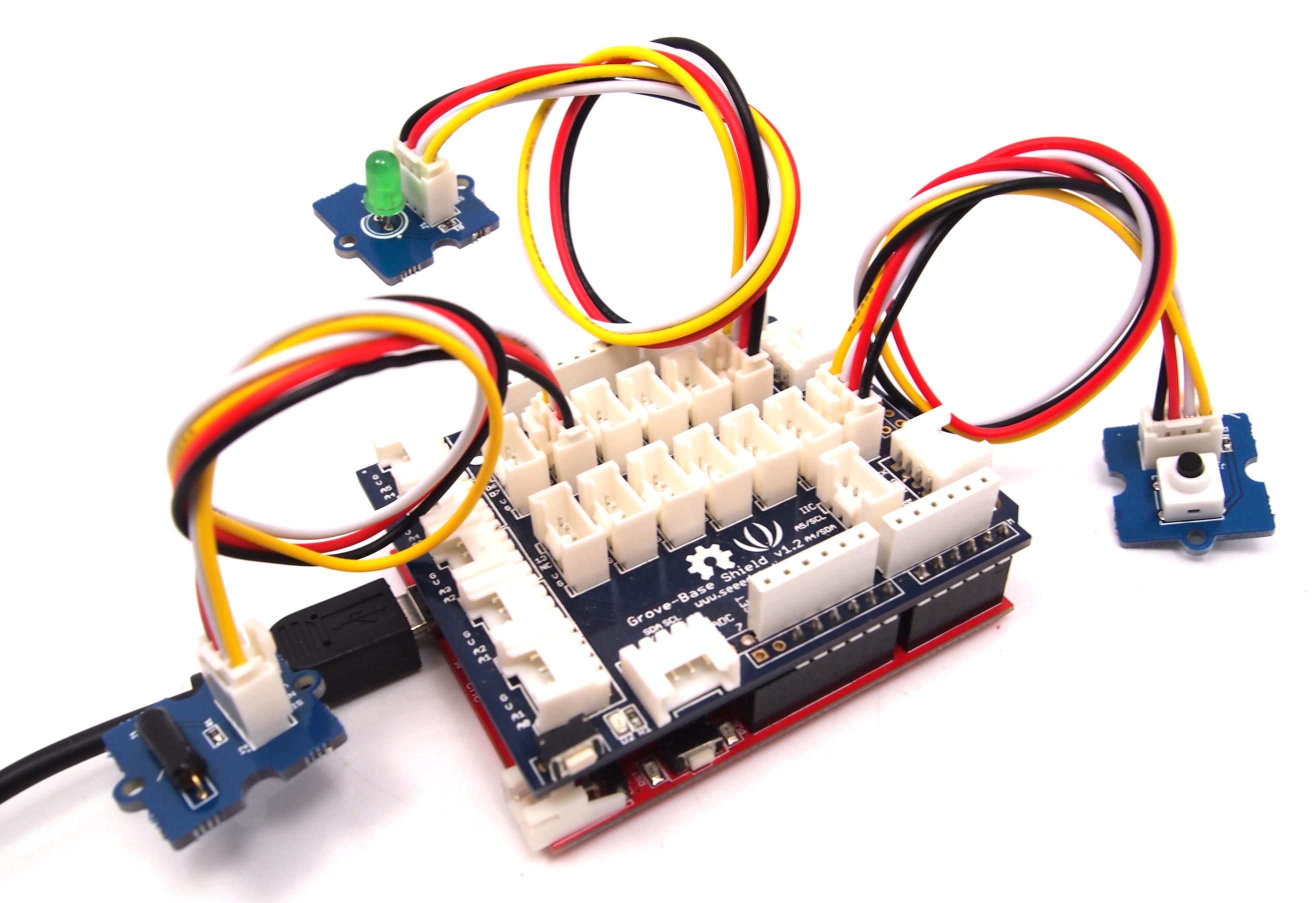
The following sketch demonstrates a simple application of using the Tilt Switch and Grove - Button to control the led.
- As the following picture indicates, the Tilt Switch is connected to digital port 5 of the Grove - Base Shield and the Grove-Button to digital port 7. The LED is connected to digital port 2. The hardware installation is as follows:
- Copy and paste code below to a new Arduino sketch.
void setup()
{
    pinMode(1, OUTPUT);
    pinMode(5, INPUT);
    pinMode(7, INPUT);
}

void loop()
{

    if (digitalRead(5)==HIGH)
    {
        digitalWrite(1, HIGH);
        delay(100);
        digitalWrite(1, LOW);
    }

    if (digitalRead(7)==HIGH)
    {
        digitalWrite(1, HIGH);
        delay(200);
        digitalWrite(1, LOW);
    }

}
- Upload the code.
- Then the LED will light when you press the button or activate the tilt-switch. Have a try!
Reference
The operating angle of Grove-Tilt Switch as shown below:

Note
The mark J1 on the Grove is the reference terminal.With Raspberry Pi
1.You should have a Raspberry Pi and a Grovepi or Grovepi+.
2.You should have completed configuring the development enviroment, otherwise follow here.
3.Connection
- Plug Tilt_Switch into grovepi socket D3 by using a grove cable.
4.Navigate to the demos’ directory:
cd yourpath/GrovePi/Software/Python/
- To see the code
nano grovepi_tilt_switch.py # "Ctrl+x" to exit #
    import time
    import grovepi

    # Connect the Grove Tilt Switch to digital port D3
    # SIG,NC,VCC,GND
    tilt_switch = 3

    grovepi.pinMode(tilt_switch,"INPUT")

    while True:
        try:
            print grovepi.digitalRead(tilt_switch)
            time.sleep(.5)

        except IOError:
            print "Error"
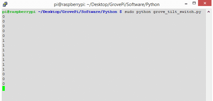
5.Run the demo.
sudo python grove_tilt_switch.py
6.Result: Put the sensor upright by one side, the SIG pin will output HIGH.
Resources
- Grove - Tilt Switch v1.0 Eagle File
- Grove - Tilt Switch v1.1 PDF File
- Grove - Tilt Switch v1.1 Eagle File
- SW200D Datasheet
| Arduino | Wio | BeagleBone | Raspberry Pi | LinkIt ONE |
|---|---|---|---|---|
Caution
The platforms mentioned above as supported is/are an indication of the module's hardware or theoritical compatibility. We only provide software library or code examples for Arduino platform in most cases. It is not possible to provide software library / demo code for all possible MCU platforms. Hence, users have to write their own software library.
Help us make it better
Welcome to the new documentation system of Seeed Studio. We have made a lot of progress comparing to the old wiki system and will continue to improve it to make it more user friendly and helpful. The improvement can't be done without your kindly feedback. If you have any suggestions or findings, you are most welcome to submit the amended version as our contributor via Github or give us suggestions in the survey below, it would be more appreciated if you could leave your email so that we can reply to you. Happy Hacking!