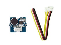
Grove - Sound Sensor
Introduction
—

Grove - Sound Sensor can detect the sound intensity of the environment. The main component of the module is a simple microphone, which is based on the LM386 amplifier and an electret microphone. This module’s output is analog and can be easily sampled and tested by a Seeeduino.

Features
- Easy to use
- Provides analog output signal
- Easily integrates with Logic modules on the input side of Grove circuits
- Grove System
Warning
This sound sensor is used to detect whether there’s sound surround or not, please don’t use the module to collect sound signal. For example, you can use it to make a sound control lamp, but not as a recording device.
Specifications
| Item | Value |
|---|---|
| Operating Voltage Range | 3.3/5 V |
| Operating Current(Vcc=5V) | 4~5 mA |
| Voltage Gain(V=6V, f=1kHz) | 26 dB |
| Microphone sensitivity(1kHz) | 52-48 dB |
| Microphone Impedance | 2.2k Ohm |
| Microphone Frequency | 16-20 kHz |
| Microphone S/N Radio | 54 dB |
Tip
More details about Grove modules please refer to Grove System
Platforms Supported
Getting Started
Note
This chapter is based on Win10 and Arduino IDE 1.6.9
This an easy-to-use module, what you need to do is to connect the signal pin (the YELLOW pin of Grove cable) to the ADC input of your controller. If there’s no internal ADC in your controller, Grove - I2C ADC is recommended.
Here we will show you how this Grove - Sound Sensor works via a simple demo. First of all, you need to prepare the below stuffs:
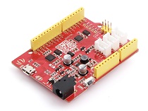
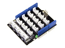
| Seeeduino V4 | Grove - Sound Sensor | Base Shield |
|---|---|---|
 |
 |
 |
| Get ONE Now | Get ONE Now | Get ONE Now |
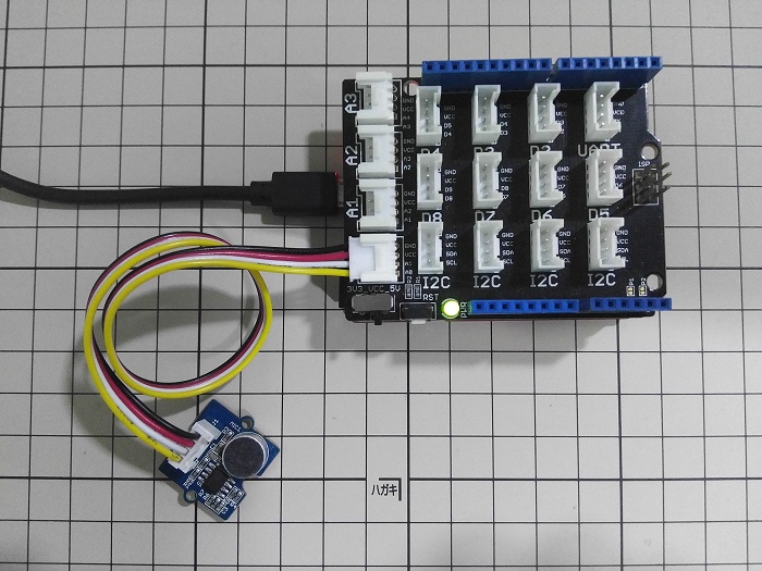
Connection
Thanks to the benefit of Grove series modules, you don’t need to make soldering or bread board, what you need to do is to connect the modules to the right port of Base Shield. For this demo, we only need one Grove module.
- Grove - Sound Sensor is an analog input module, we connect it to A0 at this demo
Upload the code to Arduino
Copy the below code to Arduino IDE.
// test code for Grove - Sound Sensor
// loovee @ 2016-8-30

const int pinAdc = A0;

void setup()
{
    Serial.begin(115200);
    //Serial.println("Grove - Sound Sensor Test...");
}

void loop()
{
    long sum = 0;
    for(int i=0; i<32; i++)
    {
        sum += analogRead(pinAdc);
    }

    sum >>= 5;

    Serial.println(sum);
    delay(10);
}
Then choose the right Board and COM port, and then click on the Upload button, this process take few seconds.
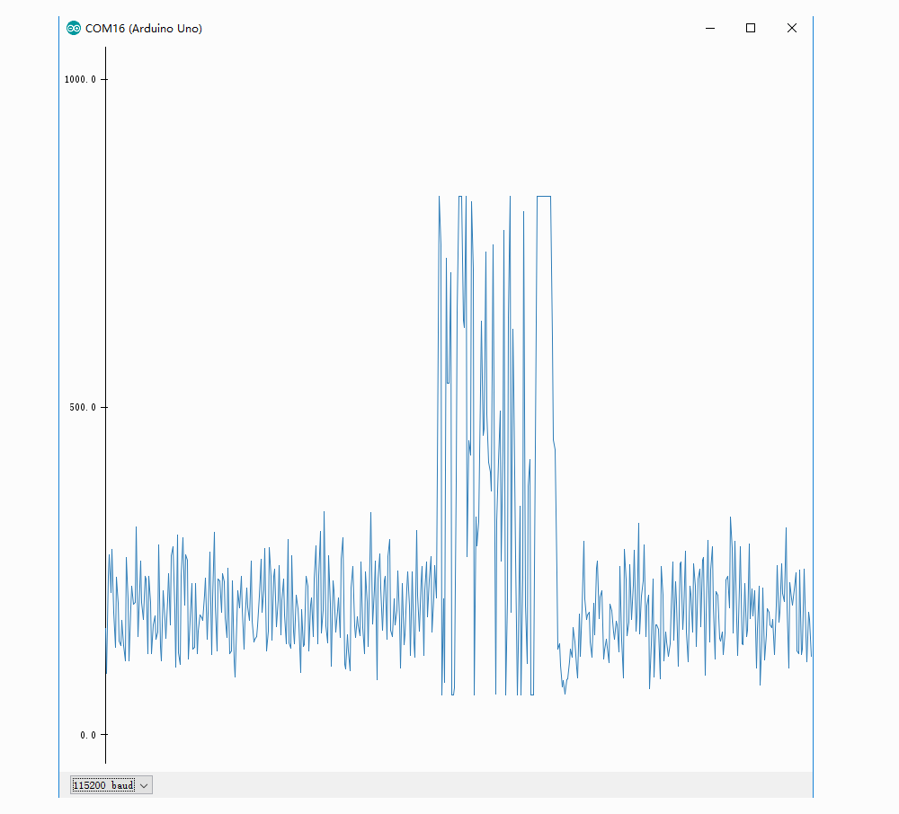
Get Raw Data
Here let’s click on Serial > Plotter to get the changing curve of the sensor. Please make a noise to view the change of the value.
Resources
- Schematic and PCB in Eagle format
- Schematic in PDF format
- PCB in PDF format
- Github Page of this Document
- LM386.PDF
| Arduino | Wio | BeagleBone | Raspberry Pi | LinkIt ONE |
|---|---|---|---|---|
Caution
The platforms mentioned above as supported is/are an indication of the module's hardware or theoritical compatibility. We only provide software library or code examples for Arduino platform in most cases. It is not possible to provide software library / demo code for all possible MCU platforms. Hence, users have to write their own software library.
Help us make it better
Welcome to the new documentation system of Seeed Studio. We have made a lot of progress comparing to the old wiki system and will continue to improve it to make it more user friendly and helpful. The improvement can't be done without your kindly feedback. If you have any suggestions or findings, you are most welcome to submit the amended version as our contributor via Github or give us suggestions in the survey below, it would be more appreciated if you could leave your email so that we can reply to you. Happy Hacking!