Grove - Rotary Angle Sensor
Introduction
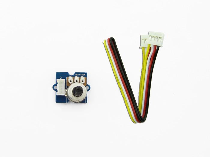
The rotary angle sensor produces analog output between 0 and Vcc (5V DC with Seeeduino) on its D1 connector. The D2 connector is not used. The angular range is 300 degrees with a linear change in value. The resistance value is 10k ohms, perfect for Arduino use. This may also be known as a “potentiometer ”.

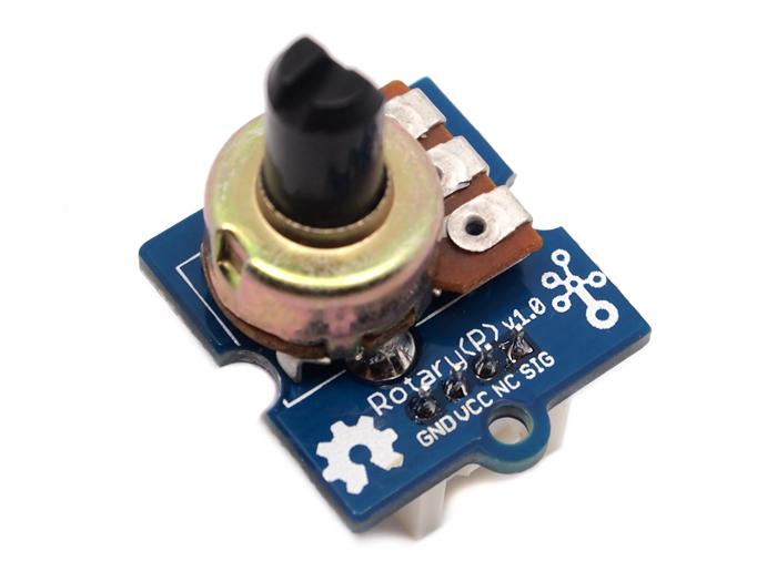
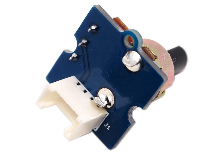
There is another product - Grove - Rotary Angle Sensor(P). What does “P” mean? “P” is for “panel mount” in this product.It is the sister version of Grove - Rotary Angle Sensor. They are identical except the Grove connecter is moved to the back so that you can easily use it as a neat and wire-free human interface device.
|
|
Features
- Grove Interface
- Easy to Use
- Grove Base Module
Tip
More details about Grove modules please refer to Grove System
Specifications
| Item | Min | Typical | Max | Unit |
|---|---|---|---|---|
| Voltage | 4.75 | 5.0 | 5.25 | VDC |
| Rotary Angle | 0 | ~ | 300 | Deg |
| Dimension | 19x19x30.1 | mm | ||
Platforms Supported
Usage
With Arduino
The following sketch demonstrates a simple application of using the rotary angle sensor to control the brightness of the LED. The degrees of Rotary Angle Sensor is 0~300 degrees, we should be converted to the corresponding voltage value in demo code for controlling the brightness of the LED.
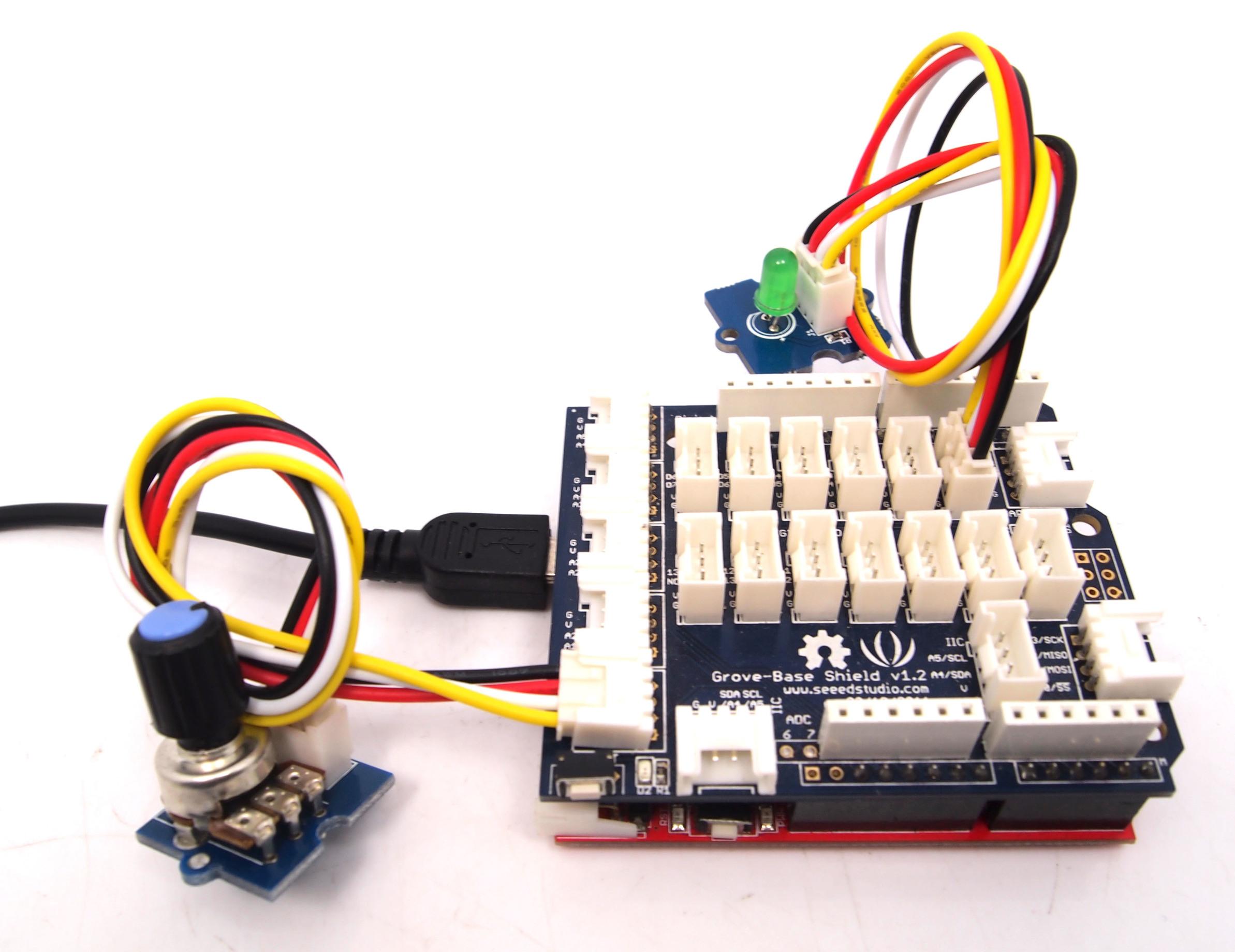
- As the picture on the below indicates, the Rotary Angle Sensor sensor is connected to Analog port A0 of the Grove - Base Shield and the LED is connected to digital port 2.
- Copy and paste code below to a new Arduino sketch.
    /******************************************************************************/
    /*macro definitions of Rotary angle sensor and LED pin*/
    #define ROTARY_ANGLE_SENSOR A0
    #define LED 2//the Grove - LED is connected to D3 of Arduino
    #define ADC_REF 5//reference voltage of ADC is 5v.If the Vcc switch on the seeeduino
                     //board switches to 3V3, the ADC_REF should be 3.3
    #define GROVE_VCC 5//VCC of the grove interface is normally 5v
    #define FULL_ANGLE 300//full value of the rotary angle is 300 degrees
    void setup()
    {
        Serial.begin(9600);
        pinsInit();
    }

    void loop()
    {
        int degrees;
        degrees = getDegree();
        Serial.println("The angle between the mark and the starting position:");
        Serial.println(degrees);

        int brightness;
        /*The degrees is 0~300, should be converted to be 0~255 to control the*/
        /*brightness of LED                                                   */
        brightness = map(degrees, 0, FULL_ANGLE, 0, 255);
        controlBrightness(brightness);

        delay(500);
    }
    void pinsInit()
    {
        pinMode(ROTARY_ANGLE_SENSOR, INPUT);
        pinMode(LED,OUTPUT);
    }

    /*PWM control brightness                        */
    /*If brightness is 0,the LED is off.            */
    /*The Greater the brightness, the brighter the LED.*/
    /*The range of brightness is 0~255              */
    void controlBrightness(int brightness)
    {
        analogWrite(LED,brightness);
    }
    /************************************************************************/
    /*Function: Get the angle between the mark and the starting position    */
    /*Parameter:-void                                                       */
    /*Return:   -int,the range of degrees is 0~300                          */
    int getDegree()
    {
        int sensor_value = analogRead(ROTARY_ANGLE_SENSOR);
        float voltage;
        voltage = (float)sensor_value*ADC_REF/1023;
        float degrees = (voltage*FULL_ANGLE)/GROVE_VCC;
        return degrees;
    }
- Upload the code.
- Then you can control the LED by rotating the sensor. Have a try!
With TI LaunchPad
Reading the Potentiometer (Rotary Angle Sensor)
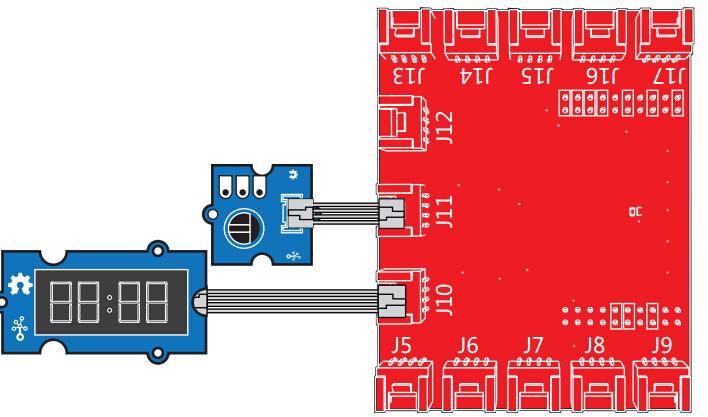
This example shows how to read the analog output coming from the Grove potentiometer module. We will be combining a few Grove modules in this example! By turning the potentiometer knob, we will display the analog reading value on the Grove 4-digital display.
    /*
      Rotary Angle Sensor
     Demonstrates analog input by reading an analog sensor on J16 of the Grove Base BoosterPack. The speed of the red LED on the LaunchPad will change depending on the position of the potentiometer knob. This example will also display the analog reading value on the Grove 4-digital display.

     The circuit:
     * Potentiometer attached to pin 24 (J6 on Grove Base BoosterPack)
     * center pin of the potentiometer to the analog pin
     * one side pin (either one) to ground
     * the other side pin to VCC (3.3V)

     * Note: Because of unstable of the voltage, the value of the rotary angle sensor
             varies slightly from run to run even you don't touch it.

     Created by Oliver Wang

     This example code is in the public domain.

     http://www.seeedstudio.com/wiki/GROVE_-_Starter_Kit_v1.1b#Grove_-_Rotary_Angle_Sensor
     */

    #include "TM1637.h"

    /* Macro Define */
    #define CLK               39                  /* 4-digital display clock pin */
    #define DIO               38                /* 4-digital display data pin */
    #define ROTARY_ANGLE_P    24               /* pin of rotary angle sensor */

    /* Global Variables */
    TM1637 tm1637(CLK, DIO);                  /* 4-digital display object */
    int analog_value = 0;                     /* variable to store the value coming from rotary angle sensor */

    int8_t bits[4] = {0};                     /* array to store the single bits of the value */

    /* the setup() method runs once, when the sketch starts */
    void setup() {

        /* Initialize 4-digital display */
        tm1637.init();
        tm1637.set(BRIGHT_TYPICAL);

    }

    /* the loop() method runs over and over again */
    void loop() {

        analog_value = analogRead(ROTARY_ANGLE_P);      /* read the value from the sensor */
        memset(bits, 0, 4);                             /* reset array when we use it */
        for(int i = 3; i >= 0; i--) {
            /* get single bits of the analog value */
            bits[i] = analog_value % 10;
            analog_value = analog_value / 10;
            tm1637.display(i, bits[i]);                 /* display by 4-digital display */
        }
        delay(100);
    }
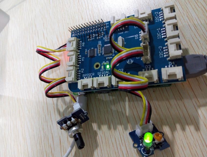
With Raspberry Pi
This example uses ADC channel 0 to get the value of the rotary angle.Then gives PWM output to change brightness of LED.
    # GrovePi + Grove Rotary Angle Sensor (Potentiometer) + Grove LED
    import time
    import grovepi

    # Connect the Grove Rotary Angle Sensor to analog port A0
    # SIG,NC,VCC,GND
    potentiometer = 0

    # Connect the LED to digital port D5
    # SIG,NC,VCC,GND
    led = 5

    grovepi.pinMode(potentiometer,"INPUT")
    grovepi.pinMode(led,"OUTPUT")
    time.sleep(1)

    # Reference voltage of ADC is 5v
    adc_ref = 5

    # Vcc of the grove interface is normally 5v
    grove_vcc = 5

    # Full value of the rotary angle is 300 degrees, as per it's specs (0 to 300)
    full_angle = 300

    while True:
        try:
            # Read sensor value from potentiometer
            sensor_value = grovepi.analogRead(potentiometer)

            # Calculate voltage
            voltage = round((float)(sensor_value) * adc_ref / 1023, 2)

            # Calculate rotation in degrees (0 to 300)
            degrees = round((voltage * full_angle) / grove_vcc, 2)

            # Calculate LED brightess (0 to 255) from degrees (0 to 300)
            brightness = int(degrees / full_angle * 255)

            # Give PWM output to LED
            grovepi.analogWrite(led,brightness)

            print "sensor_value =", sensor_value, " voltage =", voltage, " degrees =", degrees, " brightness =", brightness

        except IOError:
            print "Error"
Run the program
- Find the path to the file (according to your own path).
cd GrovePi/Software/Python/
- Run the program.
sudo python grove_rotary_angle_sensor.py
Resources
- Grove-Rotary Angle v1.2 Sensor Eagle File
- Grove-Rotary Angle Sensor Eagle File
- Github repository for Rotary Angle Sensor
| Arduino | Wio | BeagleBone | Raspberry Pi | LinkIt ONE |
|---|---|---|---|---|
Caution
The platforms mentioned above as supported is/are an indication of the module's hardware or theoritical compatibility. We only provide software library or code examples for Arduino platform in most cases. It is not possible to provide software library / demo code for all possible MCU platforms. Hence, users have to write their own software library.
Help us make it better
Welcome to the new documentation system of Seeed Studio. We have made a lot of progress comparing to the old wiki system and will continue to improve it to make it more user friendly and helpful. The improvement can't be done without your kindly feedback. If you have any suggestions or findings, you are most welcome to submit the amended version as our contributor via Github or give us suggestions in the survey below, it would be more appreciated if you could leave your email so that we can reply to you. Happy Hacking!