Grove - RTC
Introduction
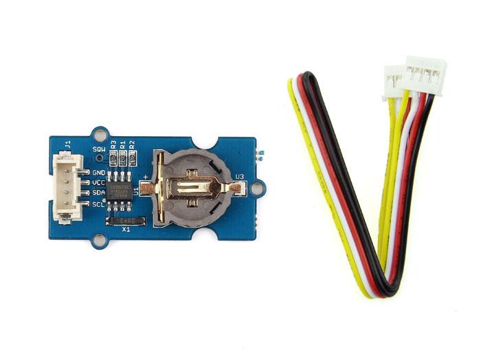
The RTC module is based on the clock chip DS1307, which supports the I2C protocol. It utilizes a Lithium cell battery (CR1225). The clock/calendar provides seconds, minutes, hours, day, date, month, and year. The end of the month date is automatically adjusted for months with fewer than 31 days, including corrections for leap years. The clock operates in either the 24-hour or 12-hour format with AM/PM indicator. And it is valid up to 2100. In order to gain a robust performance, you must put a 3-Volt CR1225 lithium cell in the battery-holder. If you use the primary power only, the module may not work normally, because the crystal may not oscillate.

Note
The battery is not included.Specifications
- PCB Size: 2.0cm*4.0cm
- Interface: 2.0mm pitch pin header
- IO Structure: SCL,SDA,VCC,GND
- ROHS: YES
- VCC:3.3~5.5V
- Logic High Level Input :2.2~VCC+0.3 V
- Logic Low Level Input :-0.3~+0.8 V
- Battery Voltage:2.0~3.5 V
Tip
More details about Grove modules please refer to Grove System
Platforms Supported
Getting Started
With Arduino
Connection
Here we will show you how this Grove - RTC works via a simple demo. First of all, you need to prepare the below stuffs:
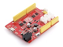
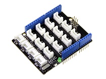
| Seeeduino V4 | Grove - RTC | Base Shield |
|---|---|---|
 |
 |
 |
| Get ONE Now | Get ONE Now | Get ONE Now |
- Connect the module to the I2C Interface of Grove- Base Shield.
- Plug Grove- Base Shield into Arduino.
- Connect Arduino to PC via a USB cable.
Note
In order to gain a robust performance, you must put a 3-Volt CR1225 lithium cell in the battery-holder. If you use the primary power only, the module may not work normally, because the crystal may not oscillate.
Note
If we don’t have the base shield, we also can directly connect the Grove-RTC to Arduino board. Please follow below connection.
| Grove-RTC | Arduino |
|---|---|
| GND | GND |
| VCC | VCC |
| SDA | A4 |
| SCL | A5 |
Software
- Download the RTC Library.
- Please follow how to install an arduino library procedures to install library.
- Open the code directly by the path: File -> Example ->RTC->SetTimeAndDisplay.

#include <Wire.h>
#include "DS1307.h"

DS1307 clock;//define a object of DS1307 class
void setup()
{
    Serial.begin(9600);
    clock.begin();
    clock.fillByYMD(2013,1,19);//Jan 19,2013
    clock.fillByHMS(15,28,30);//15:28 30"
    clock.fillDayOfWeek(SAT);//Saturday
    clock.setTime();//write time to the RTC chip
}
void loop()
{
    printTime();
}
    /*Function: Display time on the serial monitor*/
void printTime()
{
    clock.getTime();
    Serial.print(clock.hour, DEC);
    Serial.print(":");
    Serial.print(clock.minute, DEC);
    Serial.print(":");
    Serial.print(clock.second, DEC);
    Serial.print("  ");
    Serial.print(clock.month, DEC);
    Serial.print("/");
    Serial.print(clock.dayOfMonth, DEC);
    Serial.print("/");
    Serial.print(clock.year+2000, DEC);
    Serial.print(" ");
    Serial.print(clock.dayOfMonth);
    Serial.print("*");
    switch (clock.dayOfWeek)// Friendly printout the weekday
    {
        case MON:
        Serial.print("MON");
        break;
        case TUE:
        Serial.print("TUE");
        break;
        case WED:
        Serial.print("WED");
        break;
        case THU:
        Serial.print("THU");
        break;
        case FRI:
        Serial.print("FRI");
        break;
        case SAT:
        Serial.print("SAT");
        break;
        case SUN:
        Serial.print("SUN");
        break;
    }
    Serial.println(" ");
}
- Set the time. Change function arguments to current date/time. Please pay attention to arguments’ format.
clock.fillByYMD(2013,1,19);//Jan 19,2013
clock.fillByHMS(15,28,30);//15:28 30"
clock.fillDayOfWeek(SAT);//Saturday
- Upload the code.
- Open the serial to monitor the result.

With Raspberry Pi
Connection
- First, We need to prepare the below stuffs:
| Raspberry pi | Grove - RTC | Grovepi+ |
|---|---|---|
 |
|
 |
| Get ONE Now | Get ONE Now | Get ONE Now |
- Follow instruction to configure the development environment.
- Plug the sensor to grovepi+ socket i2c-x(1~3) by using a grove cable.

Software
Demo 1: Grove_i2c_rtc
- Navigate to the demos’ directory:
cd yourpath/GrovePi/Software/Python/
- To find the code
nano grove_i2c_rtc.py # "Ctrl+x" to exit #
    import time
    import grovepi

    # Connect the Grove Real Time Clock to any I2C port eg. I2C-1
    # Can be found at I2C address 0x68
    # SCL,SDA,VCC,GND

    while True:
        try:
            print grovepi.rtc_getTime()
            time.sleep(.5)

        except IOError:
            print "Error"
- Run the demo.
sudo python grove_i2c_rtc.py
- Here is the result.

Demo 2: Grove_rtc
- Use this demo to show the time in common
    /*
     * Grove-RTC.py
     * Demo for Raspberry Pi
     *
     * Copyright (c) 2014 seeed technology inc.
     * Website    : www.seeed.cc
     * Author     : Lambor
     * Create Time: Nov 2014
     * Change Log :
     *
     * The MIT License (MIT)
     *
     * Permission is hereby granted, free of charge, to any person obtaining a copy
     * of this software and associated documentation files (the "Software"), to deal
     * in the Software without restriction, including without limitation the rights
     * to use, copy, modify, merge, publish, distribute, sublicense, and/or sell
     * copies of the Software, and to permit persons to whom the Software is
     * furnished to do so, subject to the following conditions:
     *
     * The above copyright notice and this permission notice shall be included in
     * all copies or substantial portions of the Software.
     *
     * THE SOFTWARE IS PROVIDED "AS IS", WITHOUT WARRANTY OF ANY KIND, EXPRESS OR
     * IMPLIED, INCLUDING BUT NOT LIMITED TO THE WARRANTIES OF MERCHANTABILITY,
     * FITNESS FOR A PARTICULAR PURPOSE AND NONINFRINGEMENT. IN NO EVENT SHALL THE
     * AUTHORS OR COPYRIGHT HOLDERS BE LIABLE FOR ANY CLAIM, DAMAGES OR OTHER
     * LIABILITY, WHETHER IN AN ACTION OF CONTRACT, TORT OR OTHERWISE, ARISING FROM,
     * OUT OF OR IN CONNECTION WITH THE SOFTWARE OR THE USE OR OTHER DEALINGS IN
     * THE SOFTWARE.
     */

    #!/usr/bin/python
    import time
    import smbus


    bus = smbus.SMBus(1)    # 0 = /dev/i2c-0 (port I2C0), 1 = /dev/i2c-1 (port I2C1)

    class DS1307():
        def __init__(self):
            self.MON = 1
            self.TUE = 2
            self.WED = 3
            self.THU = 4
            self.FRI = 5
            self.SAT = 6
            self.SUN = 7
            self.DS1307_I2C_ADDRESS = 0x68

            print 'begin'

        def decToBcd(self, val):
            return ( (val/10*16) + (val%10) )

        def bcdToDec(self,  val):
            return ( (val/16*10) + (val%16) )

        def begin(self, news):
            print news

        def startClock(self):
            bus.write_byte(self.DS1307_I2C_ADDRESS, 0x00)
            self.second = bus.read_byte(self.DS1307_I2C_ADDRESS) & 0x7f
            bus.write_byte_data(self.DS1307_I2C_ADDRESS, 0x00, self.second)

            print 'startClock..'

        def stopClock(self):
            bus.write_byte(self.DS1307_I2C_ADDRESS, 0x00)
            self.second = bus.read_byte(self.DS1307_I2C_ADDRESS) | 0x80
            bus.write_byte_data(self.DS1307_I2C_ADDRESS, 0x00, self.second)

            print 'stopClock..'

        def setTime(self):
            data = [self.decToBcd(self.second), self.decToBcd(self.minute), \
                    self.decToBcd(self.hour), self.decToBcd(self.dayOfWeek), \
                    self.decToBcd(self.dayOfMonth), self.decToBcd(self.month), \
                    self.decToBcd(self.year)]

            bus.write_byte(self.DS1307_I2C_ADDRESS, 0x00)
            bus.write_i2c_block_data(self.DS1307_I2C_ADDRESS,0x00,data)

            print 'setTime..'

        def getTime(self):
            bus.write_byte(self.DS1307_I2C_ADDRESS, 0x00)
            data = bus.read_i2c_block_data(self.DS1307_I2C_ADDRESS,0x00)
            #A few of these need masks because certain bits are control bits
            self.second = self.bcdToDec(data[0] & 0x7f)
            self.minute = self.bcdToDec(data[1])
            self.hour = self.bcdToDec(data[2] & 0x3f)  #Need to change this if 12 hour am/pm
            self.dayOfWeek = self.bcdToDec(data[3])
            self.dayOfMonth = self.bcdToDec(data[4])
            self.month = self.bcdToDec(data[5])
            self.year = self.bcdToDec(data[6])

            print 'getTime..'

        def fillByHMS(self, _hour,  _minute,  _second):
            self.hour = _hour
            self.minute = _minute
            self.second = _second

            print 'fillByHMS..'

        def fillByYMD(self, _year,  _month,  _day):
            self.year = _year - 2000
            self.month = _month;
            self.dayOfMonth = _day

            print 'fillByYMD..'

        def fillDayOfWeek(self,  _dow):
            self.dayOfWeek = _dow

            print 'fillDayOfWeek..'

    if __name__ == "__main__":
        clock = DS1307()
        clock.fillByYMD(2015,3,5)
        clock.fillByHMS(12,42,30)
        clock.fillDayOfWeek(clock.THU)
        clock.setTime()
        while True:
            clock.getTime()
            print clock.hour, ":", clock.minute, ":", \
                    clock.second, " ", clock.dayOfMonth, "/", \
                    clock.month, "/", clock.year,"  ", "weekday", \
                    ":", clock.dayOfWeek
            time.sleep(1)
-
Create grove_rtc.py and copy codes above.
-
Run the code
sudo python grove_rtc.py
- Here is the result.

Without Grove Shield
Connection
Without Grove Shield,you can connect to Arduino by increasing an Pinout to a grove interface.
| grove | Arduino |
|---|---|
| GND | GND |
| VCC | VCC |
| SDA | SDA |
| SCL | SCL |
Resources
- [Eagle] Grove-RTC in Eagle format
- [PDF] Grove-RTC Schematic in PDF format
- [PDF] Grove-RTC PCB in PDF format
- [Library]Github repository for RTC
- [Datasheet] DS1307 Datasheet
| Arduino | Wio | BeagleBone | Raspberry Pi | LinkIt ONE |
|---|---|---|---|---|
Caution
The platforms mentioned above as supported is/are an indication of the module's hardware or theoritical compatibility. We only provide software library or code examples for Arduino platform in most cases. It is not possible to provide software library / demo code for all possible MCU platforms. Hence, users have to write their own software library.
Help us make it better
Welcome to the new documentation system of Seeed Studio. We have made a lot of progress comparing to the old wiki system and will continue to improve it to make it more user friendly and helpful. The improvement can't be done without your kindly feedback. If you have any suggestions or findings, you are most welcome to submit the amended version as our contributor via Github or give us suggestions in the survey below, it would be more appreciated if you could leave your email so that we can reply to you. Happy Hacking!