Grove - Piezo Vibration Sensor
Introduction
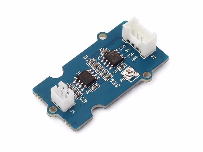
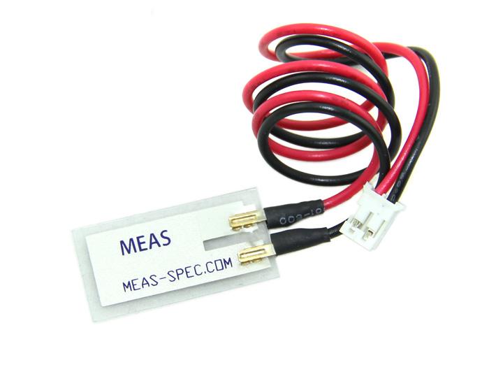
Grove-Piezo Vibration Sensor is suitable for measurements of flexibility, vibration, impact and touch. The module is based on PZT film sensor LDT0-028. When the sensor moves back and forth, a certain voltage will be generated by the voltage comparator inside of it. A wide dynamic range (0.001Hz~1000MHz) guarantees an excellent measuring performance. And, you can adjust its sensitivity by adjusting the on-board potentiometer with a screw.

Version
| Product Version | Changes | Released Date |
|---|---|---|
| Grove - Piezo Vibration Sensor V1.1 | Initial | Jul 2014 |
Features
- Standard grove socket
- Wide dynamic range:0.1Hz~180Hz
- Adjustable sensitivity
- High receptivity for strong impact
Tip
More details about Grove modules please refer to Grove System
Platforms Supported
Applications
- Vibration Sensing in Washing Machine
- Low Power Wakeup Switch
- Low Cost Vibration Sensing
- Car Alarms
- Body Movement
- Security Systems
Getting Started
Play With Arduino
Hardware
The Grove - Piezo Vibration Sensor outputs a logic HIGH when vibration was detected. We can use any of Arduino pins to read the data. Here is an example of Piezo Vibration Sensor controlling LED. When the vibration was detected, this sensor outputs a logic high signal (the sensitivity can be changed by adjusting the potentiometer), an LED lights up.
- Step 1. Prepare the below stuffs:
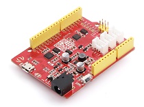
| Seeeduino V4 | Grove - Piezo Vibration | Base Shield |
|---|---|---|
 |
 |
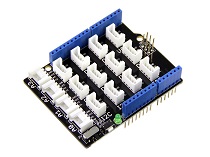 |
| Get ONE Now | Get ONE Now | Get ONE Now |
- Step 2. Connect the module to the D2 of base shield using the 4-pin grove cable, we use digital pin13 on board LED as output.
- Step 3. Plug the Basic Shield into Arduino.
- Step 4. Connect Arduino to PC by using a USB cable.

Note
It may output low level even though originally output high level when you increase the threshold voltage by clockwise adjusting the potentiometer.
Software
- Step 1. Copy and paste code below to a new Arduino sketch.
const int ledPin=13;
void setup() {
    Serial.begin(9600);
    pinMode(ledPin,OUTPUT);
}

void loop() {
    int sensorState = digitalRead(2);
    Serial.println(sensorState);
    delay(1000);
    if(sensorState == HIGH)
    {
        digitalWrite(ledPin,HIGH);
    }
    else
    {
        digitalWrite(ledPin,LOW);
    }
}
- Step 2. The LED will be on when vibration is detected.
Play With Raspberry Pi
Hardware
- Step 1. Prepare the below stuffs:
| Raspberry pi | Grove - Piezo Vibration | GrovePi_Plus |
|---|---|---|
 |
|
 |
| Get ONE Now | Get ONE Now | Get ONE Now |
- Step 2. Plug the GrovePi_Plus into Raspberry.
- Step 3. Connect Grove-Piezo Vibration to A0 port of GrovePi_Plus.
- Step 4. Connect the Raspberry to PC through USB cable.

Software
- Step 1. Follow Setting Software to configure the development environment.
- Step 2. Git clone the Github repository.
cd ~
git clone https://github.com/DexterInd/GrovePi.git
- Step 3. Excute below commands to detect the vibration.
cd ~/GrovePi/Software/Python
python grove_piezo_vibration_sensor.py
Here is the grove_piezo_vibration_sensor.py code.
import time
import grovepi

# Connect the Grove Piezo Vibration Sensor to analog port A0
# OUT,NC,VCC,GND
piezo = 0

grovepi.pinMode(piezo,"INPUT")

while True:
    try:
        # When vibration is detected, the sensor outputs a logic high signal
        print grovepi.analogRead(piezo)
        time.sleep(.5)

    except IOError:
        print "Error"
- Step 4. We will see the vibration display on terminal as below.
pi@raspberrypi:~/GrovePi/Software/Python $ python grove_piezo_vibration_sensor.py
1023
1023
1023
1023
18
17
18
17
Note
We also can use grovepi.digitalRead(2) to read the vibration status with attaching the sensor to D2 port of GrovePi.
FAQs
Please click here to see all Grove-Piezo Vibration Sensor FAQs.
Tech Support
Please do not hesitate to contact techsupport@seeed.cc if you require further information.
Resources
- [PDF] Download Wiki PDF
- [Eagle] Grove - Piezo Vibration Sensor Eagle File
- [PDF] Grove - Piezo Vibration Sensor Schematic PDF File
- [PDF] Grove - Piezo Vibration Sensor PCB PDF File
- [Datasheet] Piezo Vibration Sensor Datasheet
| Arduino | Wio | BeagleBone | Raspberry Pi | LinkIt ONE |
|---|---|---|---|---|
Caution
The platforms mentioned above as supported is/are an indication of the module's hardware or theoritical compatibility. We only provide software library or code examples for Arduino platform in most cases. It is not possible to provide software library / demo code for all possible MCU platforms. Hence, users have to write their own software library.
Help us make it better
Welcome to the new documentation system of Seeed Studio. We have made a lot of progress comparing to the old wiki system and will continue to improve it to make it more user friendly and helpful. The improvement can't be done without your kindly feedback. If you have any suggestions or findings, you are most welcome to submit the amended version as our contributor via Github or give us suggestions in the survey below, it would be more appreciated if you could leave your email so that we can reply to you. Happy Hacking!