Grove - Magnetic Switch
Introduction
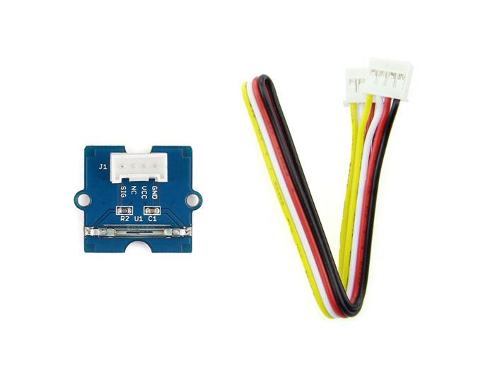
This is a Grove interface compatible Magnetic switch module. It is based on encapsulated dry reed switch CT10. CT10 is single-pole, single throw (SPST) type, having normally open ruthenium contacts. The sensor is a double-ended type and may be actuated with an electromagnet, a permanent magnet or a combination of both. The magnetic switch is a wonderful tool for designers who would like to turn a circuit on and off based on proximity.

Features
- Grove compatible interface
- 2.0cm x 2.0cm Grove module
- Minimum external parts
- 10W rating
- Rugged encapsulation
Tip
More details about Grove modules please refer to Grove System
Application Ideas
- Proximity Sensor
- Security Alarm Sensor
- Level Sensor
- Flow Sensor
- Pulse Counter
Specifications
| Items | Min | Norm | Max | Unit |
|---|---|---|---|---|
| Working Voltage | 4.75 | 5.0 | 5.25 | V |
| Switched Power | 10 | W | ||
| Switched Voltage AC,RMS value(max) | < 140 | V | ||
| Switched Current DC | < 500 | mA | ||
| Carry Current DC | < 0.5 | A | ||
| Contact Resistance | <200 | mΩ | ||
| Insulation Resistance | >106 | MΩ | ||
| Operating Temperature | -40 | - | 125 | ℃ |
| Operate Range | 10 | - | 40 | AT |
Platforms Supported
Usage
With Arduino
The SIG pin of the module output LOW normally. When a magnet approaches the switch, the magnetic switch close and the SIG pin output HIGH.
The following sketch demonstrates a simple application of using the Magnetic switch to control the led. When you put a magnet that has enough magnetic power close to the module, the switch is closed .Then the SIG pin out put a high voltage. You can use this to control the led.
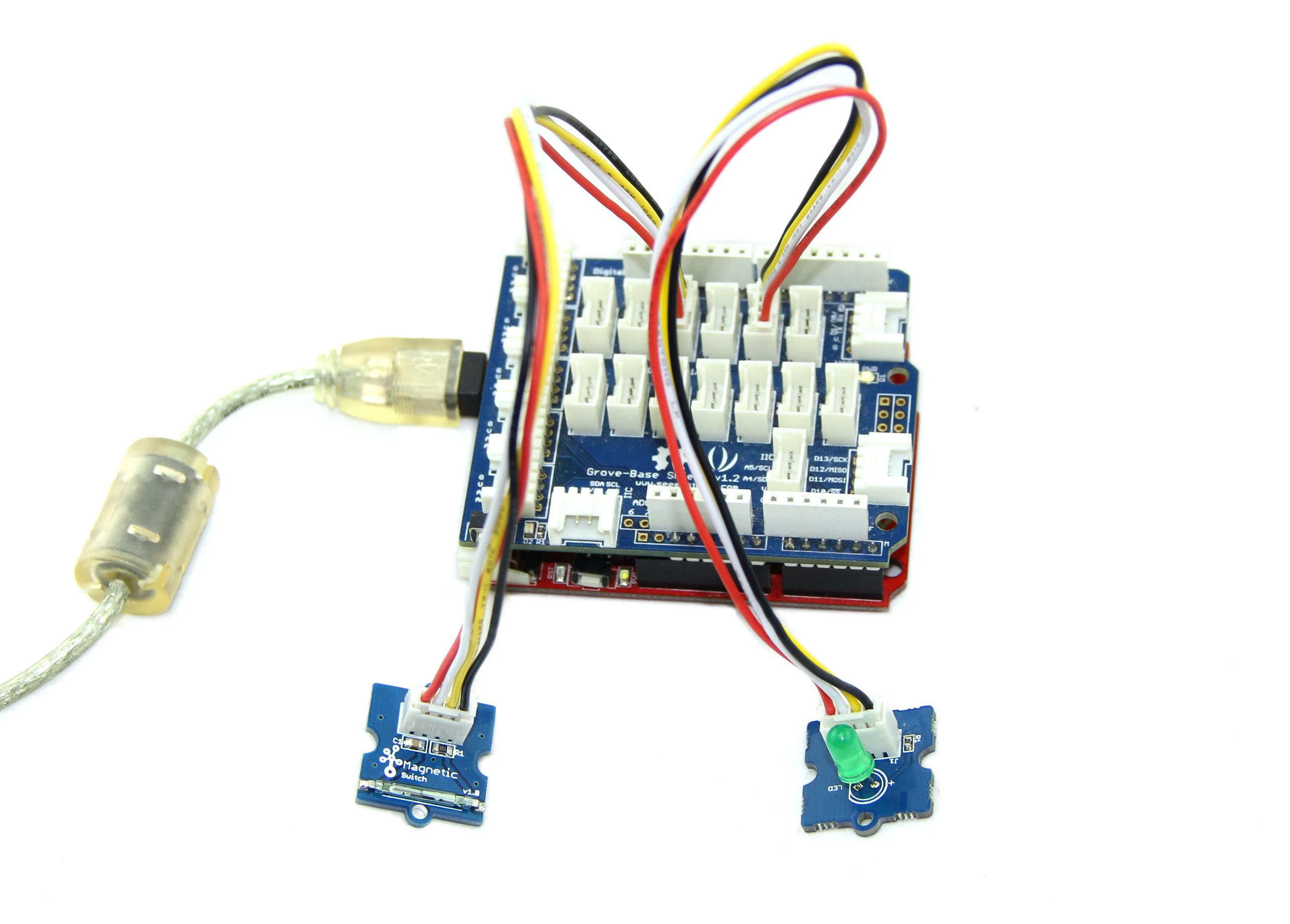
As the picture on the below indicates, the Magnetic switch is connected to digital port 9 of the Grove - Base Shield and the LED is connected to digital port 13. When a Magnet approaches the switch, the SIG pin outputs a High voltage. Then the LED lights up. The hardware installation is as follows:
- Copy and paste code below to a new Arduino sketch.
    /*******************************************************************************/

    /*macro definitions of magnetic pin and LED pin*/
    #define MAGNECTIC_SWITCH 9
    #define LED 13//the on board LED of the Arduino or Seeeduino

    void setup()
    {
        pinsInit();
    }

    void loop()
    {
        if(isNearMagnet())//if the magnetic switch is near the magnet?
        {
            turnOnLED();
        }
        else
        {
            turnOffLED();
        }
    }
    void pinsInit()
    {
        pinMode(MAGNECTIC_SWITCH, INPUT);
        pinMode(LED,OUTPUT);
    }

    /*If the magnetic switch is near the magnet, it will return ture, */
    /*otherwise it will return false                                */
    boolean isNearMagnet()
    {
        int sensorValue = digitalRead(MAGNECTIC_SWITCH);
        if(sensorValue == HIGH)//if the sensor value is HIGH?
        {
            return true;//yes,return ture
        }
        else
        {
            return false;//no,return false
        }
    }
    void turnOnLED()
    {
        digitalWrite(LED,HIGH);
    }
    void turnOffLED()
    {
        digitalWrite(LED,LOW);
    }
- Upload the code.
- Then the LED light when there is Magnetic approaches the switch. Have a try!
With Raspberry Pi
1.You should have a raspberry pi and a grovepi or grovepi+.
2.You should have completed configuring the development enviroment, otherwise follow here.
3.Connection
- Plug the Magnet Switch to grovepi socket D3 by using a grove cable.
4.Navigate to the demos’ directory:
cd yourpath/GrovePi/Software/Python/
- To see the code (this demo has the same usage with tilt switch)
nano grovepi_tilt_switch.py # "Ctrl+x" to exit #
    import time
    import grovepi

    # Connect the Grove Tilt Switch to digital port D3
    # SIG,NC,VCC,GND
    tilt_switch = 3

    grovepi.pinMode(tilt_switch,"INPUT")

    while True:
        try:
            print grovepi.digitalRead(tilt_switch)
            time.sleep(.5)

        except IOError:
            print "Error"
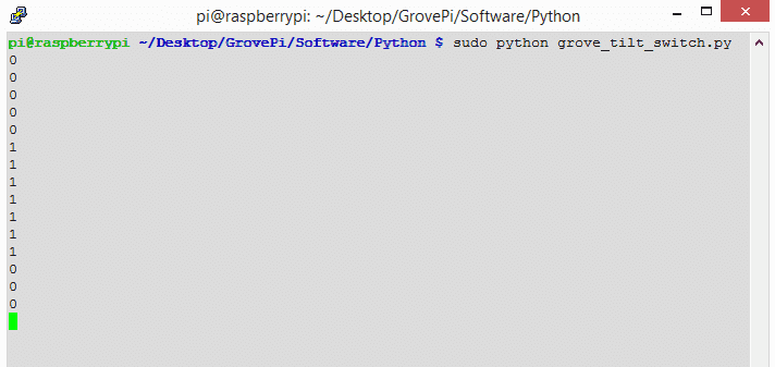
5.Run the demo.
sudo python grove_tilt_switch.py
6.Result
Put a magnet upon the sensor, the SIG pin will output HIGH.
Resources
- Grove-Magnetic Switch v0.9 Eagle File
- CT10 Datasheet
- Grove-Magnetic Switch v1.3 Eagle File
- Grove-Magnetic Switch v1.3 PDF File
| Arduino | Wio | BeagleBone | Raspberry Pi | LinkIt ONE |
|---|---|---|---|---|
Caution
The platforms mentioned above as supported is/are an indication of the module's hardware or theoritical compatibility. We only provide software library or code examples for Arduino platform in most cases. It is not possible to provide software library / demo code for all possible MCU platforms. Hence, users have to write their own software library.
Help us make it better
Welcome to the new documentation system of Seeed Studio. We have made a lot of progress comparing to the old wiki system and will continue to improve it to make it more user friendly and helpful. The improvement can't be done without your kindly feedback. If you have any suggestions or findings, you are most welcome to submit the amended version as our contributor via Github or give us suggestions in the survey below, it would be more appreciated if you could leave your email so that we can reply to you. Happy Hacking!