Grove - Electricity Sensor
Introduction
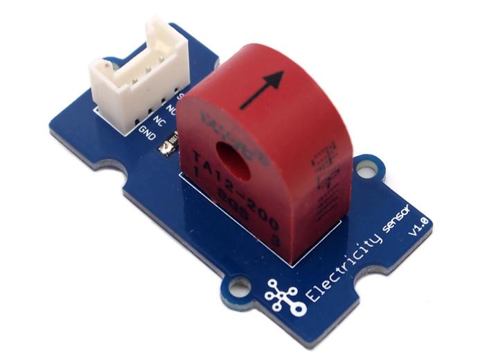
The Electricity sensor module is a member of Grove. It is based on the TA12-200 current transformer which can transform the large AC into small amplitude. You can use it to test large alternating current up to 5A.

Features
- Grove compatible interface
- Maximum 5A input
- High accuracy
- Small size
Tip
More details about Grove modules please refer to Grove System
Application Ideas
- Alternating current measurement
- Device condition monitoring
Specification
Key Specification
| Items | Min |
|---|---|
| PCB Size | 2.0cm*4.0cm |
| Interface | 2.0mm pitch pin header |
| IO Structure | SIG,NC,NC,GND |
| RoHS | YES |
Electronic Characteristics
| Items | Min | Norm | Max | Unit |
|---|---|---|---|---|
| Transformation ratio | - | 2000:1 | - | - |
| Input Current | 0 | - | 5 | A |
| Output Current | 0 | - | 2.5 | mA |
| Sampling Resistance | - | 800 | - | Ω |
| Sampling Voltage | 0 | - | 2 | V |
| Working Frequency | 20 | - | 20K | HZ |
| Nonlinear scale | - | - | 0.2% | - |
| Phase Shift | - | - | 5’ | - |
| Operating Temperature | -55 | - | 85 | ℃ |
| Dielectric strength | - | 6 | - | KVAC/1min |
Platforms Supported
Usage
With Arduino
The following sketch demonstrates a simple application of measuring the amplitude of the alternating voltage. The SIG pin will output a alternating voltage based on the alternating current being measured. You can measure the value using ADC.
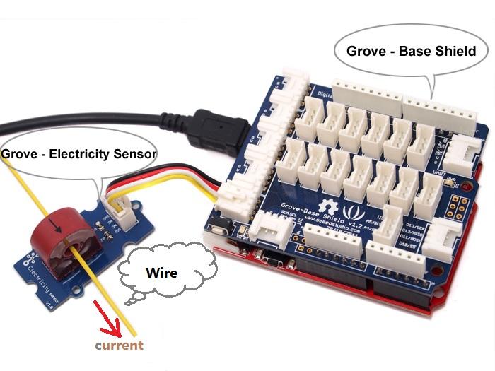
- Connect the module to the analog A0 of Grove - Base board.
- Put the alternating current wire through the hole of the current transformer.
- Copy and paste code below to a new Arduino sketch.
    /****************************************************************************/
    //  Function: Measure the amplitude current of the alternating current and
    //            the effective current of the sinusoidal alternating current.
    //  Hardware: Grove - Electricity Sensor
    //  Date:    Jan 19,2013
    //  by www.seeedstudio.com
    #define ELECTRICITY_SENSOR A0 // Analog input pin that sensor is attached to

    float amplitude_current;               //amplitude current
    float effective_value;       //effective current

    void setup()
    {
        Serial.begin(9600);
        pins_init();
    }
    void loop()
    {
        int sensor_max;
        sensor_max = getMaxValue();
        Serial.print("sensor_max = ");
        Serial.println(sensor_max);
        //the VCC on the Grove interface of the sensor is 5v
        amplitude_current=(float)sensor_max/1024*5/800*2000000;
        effective_value=amplitude_current/1.414;//minimum_current=1/1024*5/800*2000000/1.414=8.6(mA)
                            //Only for sinusoidal alternating current
        Serial.println("The amplitude of the current is(in mA)");
        Serial.println(amplitude_current,1);//Only one number after the decimal point
        Serial.println("The effective value of the current is(in mA)");
        Serial.println(effective_value,1);
    }
    void pins_init()
    {
        pinMode(ELECTRICITY_SENSOR, INPUT);
    }
    /*Function: Sample for 1000ms and get the maximum value from the SIG pin*/
    int getMaxValue()
    {
        int sensorValue;             //value read from the sensor
        int sensorMax = 0;
        uint32_t start_time = millis();
        while((millis()-start_time) < 1000)//sample for 1000ms
        {
            sensorValue = analogRead(ELECTRICITY_SENSOR);
            if (sensorValue > sensorMax)
            {
                /*record the maximum sensor value*/
                sensorMax = sensorValue;
            }
        }
        return sensorMax;
    }
- Upload the code.
Note
The minimum effective current that can be sensed by the code can be calculated using the equation below. minimum_current=1/1024*5/800*2000000/1.414=8.6(mA).- Open the serial monitor, The results is as follows:

With Raspberry Pi
1.You should have got a raspberry pi and a grovepi or grovepi+.
2.You should have completed configuring the development enviroment, otherwise follow here.
3.Connection
- Plug the sensor to grovepi socket A0 by using a grove cable.
4.Navigate to the demos’ directory:
cd yourpath/GrovePi/Software/Python/
- To see the code
nano grove_electricity_sensor.py # "Ctrl+x" to exit #
    import time
    import grovepi

    # Connect the Grove Electricity Sensor to analog port A0
    # SIG,NC,NC,GND
    sensor = 0

    grovepi.pinMode(sensor,"INPUT")

    # Vcc of the grove interface is normally 5v
    grove_vcc = 5

    while True:
        try:
            # Get sensor value
            sensor_value = grovepi.analogRead(sensor)

            # Calculate amplitude current (mA)
            amplitude_current = (float)(sensor_value / 1024 * grove_vcc / 800 * 2000000)

            # Calculate effective value (mA)
            effective_value = amplitude_current / 1.414

            # minimum_current = 1 / 1024 * grove_vcc / 800 * 2000000 / 1.414 = 8.6(mA)
            # Only for sinusoidal alternating current

            print "sensor_value", sensor_value
            print "The amplitude of the current is", amplitude_current, "mA"
            print "The effective value of the current is", effective_value, "mA"
            time.sleep(1)

        except IOError:
            print "Error"
5.Run the demo.
sudo python grove_electricity_sensor.py
Resources
| Arduino | Wio | BeagleBone | Raspberry Pi | LinkIt ONE |
|---|---|---|---|---|
Caution
The platforms mentioned above as supported is/are an indication of the module's hardware or theoritical compatibility. We only provide software library or code examples for Arduino platform in most cases. It is not possible to provide software library / demo code for all possible MCU platforms. Hence, users have to write their own software library.
Help us make it better
Welcome to the new documentation system of Seeed Studio. We have made a lot of progress comparing to the old wiki system and will continue to improve it to make it more user friendly and helpful. The improvement can't be done without your kindly feedback. If you have any suggestions or findings, you are most welcome to submit the amended version as our contributor via Github or give us suggestions in the survey below, it would be more appreciated if you could leave your email so that we can reply to you. Happy Hacking!