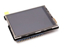
2.8'' TFT Touch Shield v2.0
Introduction
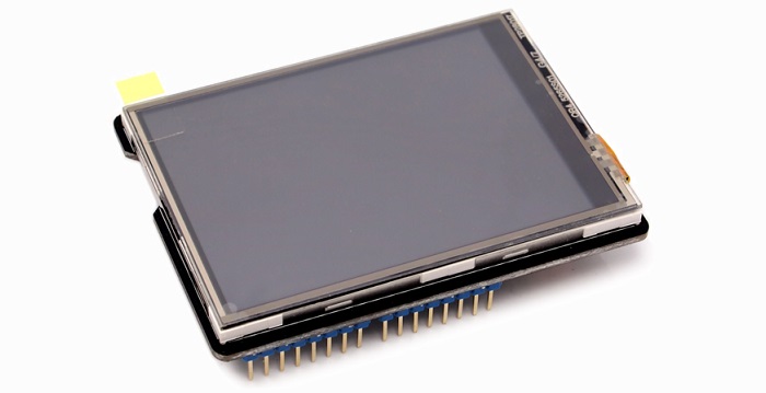
TFT Touch Shield V2.0 is a resistive touch screen, compatible with Arduino/Seeeduino/Arduino Mega platforms. It can be used as display device or sketch pad. Compared with the previous version, 2.8’‘TFT Touch Shield V1.0, we upgraded the screen driver to a more professional chip, ILI9341 driver, providing different pin-saving SPI communication without sacrificing the data transmitting speed. Due to the communication method change, programs developed for the original version are needed for modification before being transplanted to the new version. With a SD card module integrated on this shield, this shield reserves capability for other expansions of your project.

Features
- Big screen with easy and comfortable experience
- Backlight controllable via programming
- 65k rich colors display
- SPI pin-saving communication method
- Full screen touch active range
Specification
| Item | Value |
|---|---|
| Working Voltage | 5 V |
| Resolution | 320 x 240 |
| Colors | 65k |
Compatibility
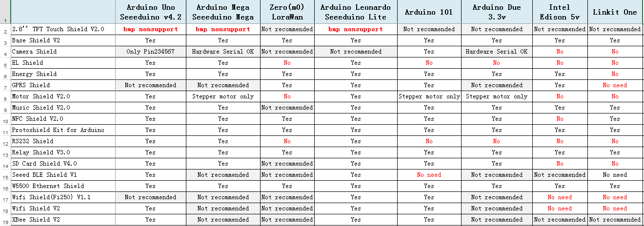
We have produced a lot of extension boards that can make your platform board more powerful, however not every extension board is compatible with all the platform boards, here we use a table to illustrate how are those boards compatible with platform board.
Note
Please note that “Not recommended” means that it might have chance to work with the platform board however requires extra work such as jump wires or rewriting the code. If you are interested in digging more, welcome to contact with techsupport@seeed.cc.
Click to see full picture
Application Ideas
- Game
- Sensor Hub
- Human Machine Interface
- Smart House
Here are some awesome projects for your reference. If you have project want to add to this chapter, please feel free to contact loovee@seeed.cc.
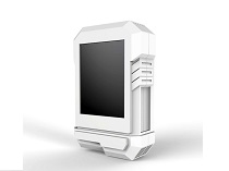
| Arduino Phone | Facebook Monitor | Instrucatbles Monitor |
|---|---|---|
 |
 |
 |
| Make it Now! | Make it Now! | Make it Now! |
Pin Map
Note
You can use the NOT USED pins to control the others module.
Digital Pins
| Pin Name | Function |
|---|---|
| D0 | NOT USED |
| D1 | NOT USED |
| D2 | NOT USED |
| D3 | NOT USED |
| D4 | TF_CS |
| D5 | TFT_CS |
| D6 | TFT_DC |
| D7 | BACKLIGHT(Selectable) |
| D8 | NOT USED |
| D9 | NOT USED |
| D10 | NOT USED |
| D11 | SPI_MOSI |
| D12 | SPI_MISO |
| D13 | SPI_SCK |
Analog Pins
| Pin Name | Function |
|---|---|
| A0 | TOUCH PANEL |
| A1 | TOUCH PANEL |
| A2 | TOUCH PANEL |
| A3 | TOUCH PANEL |
| A4 | NOT USED |
| A5 | NOT USED |
Getting Started
Note
This getting started is based on Win10 and Arduino IDE 1.6.9 environment.
We will show you how this display works, please prepare materials as below to start.
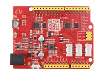
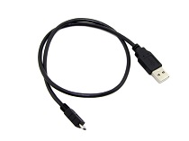
| Seeeduino V4 | 2.8 TFT Touch Shield V2 | Micro USB Cable |
|---|---|---|
 |
 |
 |
| More Details | More Details | More Details |
Download Arduino Library
This library supports below platforms:
- Arduino/Genuino UNO
- Seeeduino V3/4.0/4.2
- Arduino/Genuino Mega
- Arduino Leonardo
- Seeeduino Lite/Clio/Lotus
- LinkIt ONE(Touch panel does not work)
Click to download the Touch Screen Driver,then please click on below button to download the library and install it, if you don’t know how to install an Arduino library, please refer to the tutorial (HOW TO INSTALL AN ARDUINO LIBRARY).

This library includes below examples,
- drawCircle
- drawLines
- drawNumber
- drawRectangle
- paint
- shapes
- text
- tftbmp
- tftbmp2
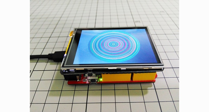
We use example ‘shapes’ for this demo.
Connect the cables and Upload the code
Step1. Insert the TFT_Touch_Shield_V2 board to Seeeduino,
Step2. Connect your Seeeduino board to computer with USB cable
Step3. Open Arduino IDE, Select the correct COM port and Boards(in this example we use Seeeduino V4)
Step4. Click on File > Examples > TFT_Touch_Shield_V2-master > shapes to open the code. Upload the example to Seeeduino.
 If you have any question about how to upload the code, please refer here for more details.
Backlight
The backlight is always default on, if you want to change the backlight, you need to do some hacking on the board. Please look at the back side of the board. There’s a BACKLIGHT label. One side is named as ON, and the other side is named D7. We need to cut the wire between middle pad and ON pad, solder middle pad with D7 pad. As shown below.

Then you can control the backlight via D7.
To open backlight: digitalWrite(7, HIGH);
To close backlight: digitaWrite(7, LOW);
Warning
Please be careful when use a box cutter and soldering iron.
Resources
- Schematic and PCB in Eagle format
- Schematic in PDF format
- PCB in PDF format
- Library at Github page
- Github page of this document
Help us make it better
Welcome to the new documentation system of Seeed Studio. We have made a lot of progress comparing to the old wiki system and will continue to improve it to make it more user friendly and helpful. The improvement can't be done without your kindly feedback. If you have any suggestions or findings, you are most welcome to submit the amended version as our contributor via Github or give us suggestions in the survey below, it would be more appreciated if you could leave your email so that we can reply to you. Happy Hacking!